Leonton EG5-0800 Series User Manual Download Page 10


LED Indicators 

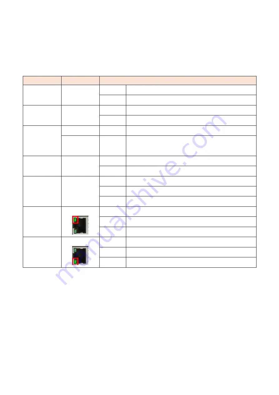
There are LED light indicators located on the front panel of the industrial Ethernet switch that 

display the power status and network status. Each LED indicator has a different color and has 

its own specific meaning, see below in Table 2.1 

LED 

Color 

Description 

P1 

Green 

On 

Power input 1 is active 

Off 

Power input 1 is inactive 

P2 

Green 

On 

Power input 2 is active 

Off 

Power input 2 is inactive 

FAULT 

Green 

On 

No event happened 

Red 

On 

1.


Power input 1 or 2 is inactive 

2.


Port link-down/Broken 

MASTER 

Green 

On 

ERPS Owner Mode (Ring Master) is ready 

Off 

ERPS Owner Mode is not active 

RING 

Green 

On 

ERPS Ring Network is active and works well 

Flashing 

ERPS Ring works abnormally or misconfigure 

Off 

ERPS Ring Network is not active 

1G 

(LAN Port 1-8) 

Green 


On 

Connected to network, 1000Mbps 

Flashing 

Networking is active 

Off 

Not connected to network 

10/100 

(LAN Port 1-8) 

Green 


On 

Connected to network, 10/100Mbps 

Flashing 

Networking is active 

Off 

Not connected to network 

Table 2.1: LED Indicators 


Summary of Contents for EG5-0800 Series

Page 1: ...LEONTON EG5 0800 Series EG5 0800 EG5 0800 T User Manual...

Page 2: ...t not limited to the implied warranties of merchantability and fitness for a particular purpose Leonton Technologies Co Ltd may make improvements and or changes to the product and or specifications of...

Page 3: ...he grantee of this device could void the user s authority to operate the equipment D claration FCC Cet quipement a t test et reconnu conforme aux limites de la classe A pour les quipements num riques...

Page 4: ...equired to take adequate measures CE Mark Avertissement Ceci est un produit de classe A Dans un environnement domestique ce produit peut tre utilis en pr sence d interf rences radio This document is t...

Page 5: ...Physical Dimensions 3 Front Panel 4 Top View 4 LED Indicators 5 Ethernet Ports 6 Cabling 7 Wiring the Power Inputs 7 Wiring the Fault Alarm Contact 8 Grounding Note 8 Mounting Installation 9 DIN Rail...

Page 6: ...erature of 10 to 65 C and another with a wide operating temperature of 40 to 75 C this series is designed to meet any needs for industrial automation outdoor application and harsh environments Key Fea...

Page 7: ...un dispositif de protection sur l entr e d alimentation Fourniture par courant industriel homologu UL Les sp cifications mat rielles les ports les informations de c blage et l installation du c blage...

Page 8: ...3 Hardware Description Physical Dimensions Figure 2 1 below shows the physical dimensions of EG5 0800 series W x H x D is 54mm x 142mm x 99mm Figure 2 1 Physical Dimensions...

Page 9: ...Front Panel Top View Figure 2 3 below shows the top panel of the EG5 0800 series switch that is equipped with one 6 pin removal terminal block connector for dual DC power inputs 12 48VDC Figure 2 3 T...

Page 10: ...s inactive FAULT Green On No event happened Red On 1 Power input 1 or 2 is inactive 2 Port link down Broken MASTER Green On ERPS Owner Mode Ring Master is ready Off ERPS Owner Mode is not active RING...

Page 11: ...raight Through Cable Pin Number Signal Pin Number Signal Pin Number Signal Pin Number Signal 1 RX 3 TX 1 RX 1 TX 2 RX 6 TX 2 RX 2 TX 3 TX 1 RX 3 TX 3 RX 6 TX 2 RX 6 TX 6 RX Table 2 2 1000BASE T RJ 45...

Page 12: ...rt the positive and negative wires into the PWR1 V1 V1 and PWR2 V2 V2 contacts on the terminal block connector as shown below in Figure 2 4 Figure 2 4 Power Terminal Block Step 2 Tighten the wire clam...

Page 13: ...1 to Pin 5 and Pin 2 to Pin 6 to eliminate power fault alarm Attention Le calibre des fils du bornier doit tre compris entre 12 et 24 AWG Si vous n utilisez qu une seule source d alimentation jumelez...

Page 14: ...ure 3 1 The Rear Side of the Switch and DIN Rail Bracket Follow the steps below to learn how to hang the industrial Ethernet switch Step 1 Use the screws to install the DIN Rail bracket on the rear si...

Page 15: ...ull down the bracket on to the rail as shown below in Figure 3 3 Figure 3 3 Stable the Switch on DIN Rail Step 5 Check if the bracket is mounted tightly on the rail Step 6 To remove the industrial Eth...

Page 16: ...strial Ethernet switch Step 3 Use the screws to screw the wall mounting bracket on the industrial Ethernet switch Step 4 Use the hook holes at the corners of the wall mounting bracket to hang the indu...

Page 17: ...ring the Power Inputs section Please refer to the LED Indicators section for LED light indication Step 5 Prepare the twisted pair straight through category 5 cable for Ethernet connection Step 6 Inser...

Page 18: ...st me int grant l quipement est de la responsabilit de l assembleur du syst me Caution This is an OPEN TYPE module and should be installed in a final safety enclosure characteristic Attention Il s agi...

Page 19: ...which help to identity if any problems exist Please refer to the LED Indicators section for LED light indication If the power indicator LED does not turn on when the power cord is plugged in the user...

Reviews: