5
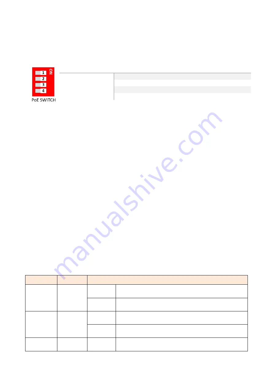
PoE Dip Switch
The 4-pin Dip Switch on the front panel of the Ethernet Switch works as the PoE Controller for PoE
Port 1~Port 4.
On
Off
PoE DIP Switch 1
Enable Port 1 PoE Function
Disable Port 1 PoE Function
PoE DIP Switch 2
Enable Port 2 PoE Function
Disable Port 2 PoE Function
PoE DIP Switch 3
Enable Port 3 PoE Function
Disable Port 3 PoE Function
PoE DIP Switch 4
Enable Port 4 PoE Function
Disable Port 4 PoE Function
Relay Contact Alarm Warning
2-pin 1*24VDC@1A resistive normal open on 6-pin terminal block.
The relay contact alarm will be triggered when anyone of the listed events occurs.
Key trigger event 1: Power-1 or Power-2 is inactive
Key trigger event 2: PoE total loading >100% PoE output budget
Key trigger event 3: PoE over current per port
Key trigger event 4: Cable short per port
Key trigger event 5: One of the channels in Dual PD fail
[Notice] When the relay is triggered because of Event 2~5, the relay contact alarm, will update
the status every 30 seconds. If there’s no event happening for 30 seconds, the relay contact alarm
will be turn off. If the user disables the failed PoE port by removing the cable or Dip Switch
manually, the relay will be recovered immediately.
LED Indicators
There are LED light indicators located on the front panel of the industrial Ethernet switch that
display the power status and network status. Each LED indicator has a different color and has its
own specific meaning, see below in Table 2.1.
LED
Color
Description
P1
Green
On
Power input 1 is active
Off
Power input 1 is inactive
P2
Green
On
Power input 2 is active
Off
Power input 2 is inactive
Fault
Off
Off
No trigger events occur

