7
Data transfer
54
Lenze · E94AYCER communication module (PROFINET®) · Communication Manual · DMS 11.0 EN · 04/2016 · TD17
_ _ _ _ _ _ _ _ _ _ _ _ _ _ _ _ _ _ _ _ _ _ _ _ _ _ _ _ _ _ _ _ _ _ _ _ _ _ _ _ _ _ _ _ _ _ _ _ _ _ _ _ _ _ _ _ _ _ _ _ _ _ _ _
7
Data transfer
PROFINET transmits parameter data, configuration data, diagnostic data, alarm messages, and
process data between the host (I/O controller) and the inverters that are part of the fieldbus (I/O
devices). Depending on their time-critical behaviour, the data are transmitted via corresponding
communication channels.
Communication channels
The process data channel transmits process data.
• The process data serve to control the inverter.
• The transmission of process data is time-critical.
• Process data are transmitted cyclically between the I/O controller and the I/O devices that are
part of the fieldbus according to the Provider/Consumer model (continuous exchange of
current input and output data).
• The I/O controller can directly access the process data. In the PLC, for instance, the data are
directly assigned to the I/O area.
• Up to 32 process data words (64 bytes) per direction can be exchanged.
• Process data are not saved in the inverter.
• Process data are e.g. setpoints, actual values, control words, and status words.
Parameter data are transmitted via the acyclic channel.
• The transmission of parameter data is usually not time-critical.
• The access to the parameter data depends on the PROFIdrive profile.
• Examples of parameter data are operating parameters, motor data, and diagnostic information.
• The acyclic channel provides access to all Lenze codes.
• Parameter data changes must be saved via code
C00002
of the Servo Drives 9400.
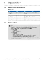
Note!
Please observe the direction of the flow of information!
Process input data (Rx data):
• Process data from the inverter (IO device) to the IO controller
Process output data (Tx data):
• Process data from the IO controller to the inverter (IO device)


