background image

S94P01B

52

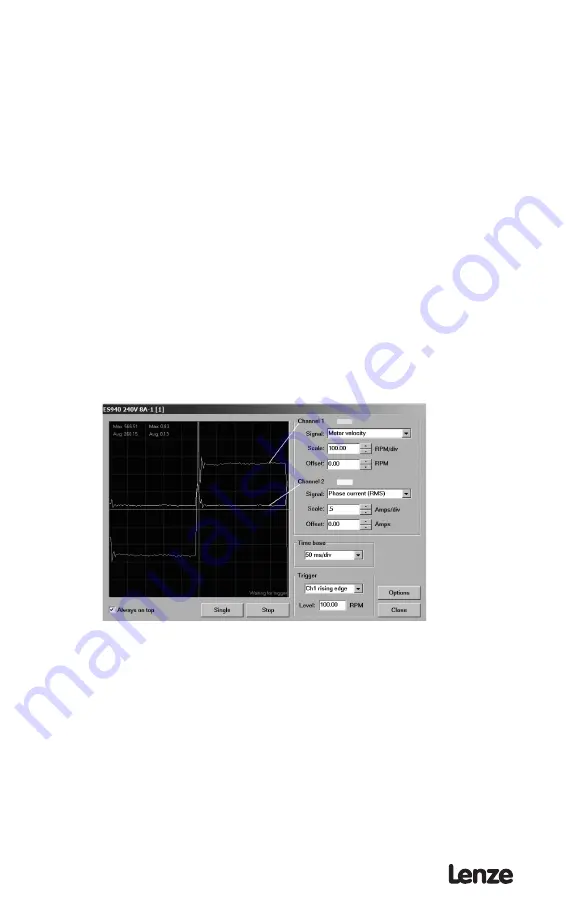
  7.  On the Scope tool select:
 

  •  Channel 1:  

“Motor Velocity” 


  •  Scale:    

100 Rpm/Volt


  •  Channel 2:  

“Phase Current (RMS)”


  •  Scale:    

Motor peak current parameter / 3 


  •  Timebase:   

50mS


  •  Trigger:  

Channel 1, Rising


  •  Trigger level:  

100 Rpm


   (Choose closest integer value: if 10A/3=3.33(3) choose 3A)

  8.  Select “Compensation” from the Node tree. Set “Gain Setting” to “-2” if the 

motor is equipped with an encoder and to “-4”  if the motor is equipped with a 
resolver.

  9.  Set the Velocity P-gain to 5000 and the Velocity I-gain to 20.
10.  Apply voltage to IN_A3 input and press F5 on the keyboard. Alternatively you 

can use menu “Indexer” -> “Run” or use button on the toolbar.

11.  If the motor vibrates uncontrollably, disable the drive, rest P-Gain to 1000, 

and re-enable the drive.

12.  Slowly increase the “Velocity P-gain” and observe the motor velocity 

waveform. Increasing the P-gain should increase the angle of the 
acceleration edge of the wave form. Continue increasing the P-gain to get 
the leading edge of the wave form as vertical as possible and stop once 
you start to get a slight overshoot. The current wave form should be spiking 
during the acceleration segment of the move.  Continue to increase the P-gain 
until instability starts to appear in the waveform. 


S949


Stop increasing the gain once you see oscillation appearing on either the 
current waveform or velocity waveform flat portion. Then lower the P-gain 
until the oscillation disappears

Summary of Contents for PositionServo 940

Page 1: ...Model 940 USERS MANUAL S94P01B S929...

Page 2: ...y kind with respect to this material including but not limited to the implied warranties of its merchantability and tness for a given purpose AC Tech assumes no responsibility for any errors that may...

Page 3: ...e 16 5 1 4 P4 Motor Feedback second loop encoder input 17 5 1 5 P5 24 VDC Back up Power Input 19 5 1 6 P6 Braking Resistor and DC Bus 19 5 1 7 Connectors and Wiring Notes 19 5 1 8 P11 Resolver interfa...

Page 4: ...Enable switch function 40 6 3 21 User Units 40 6 4 Communication 40 6 4 1 IP Setup 40 6 4 2 RS 485 con guration 40 6 4 3 Modbus baud rate 40 6 4 4 Modbus reply delay 40 6 5 Analog I O Group 40 6 5 1...

Page 5: ...n guration of the PositionServo 48 8 3 Position mode operation gearing 50 8 4 Dual loop feedback 50 8 5 Enabling the PositionServo 51 8 6 Tuning in velocity mode 51 8 7 Tuning in position mode 53 9 Sa...

Page 6: ...of impending danger Consequences if disregarded Death or severe injuries Warning of a general danger WARNING Warns of potential very hazardous situations Consequences if disregarded Death or severe in...

Page 7: ...s including analog voltage RS485 interface PPP and Modbus RTU Ethernet interface CANopen interface digital pulse train and master encoder reference The control will operate in current torque velocity...

Page 8: ...only for industrial purposes Drive systems with E94P servo inverters comply with the EMC Directive if they are installed according to the guidelines of CE typical drive systems can be used for operat...

Page 9: ...s voltage for operation on 50 60 Hz AC supplies 48 Hz 0 62Hz 0 2 Connection of 120VAC 45 V 132 V to input power terminals L1 and N on these models doubles the voltage on motor output terminals U V W f...

Page 10: ...th Up to 200 Hz Accuracy 1 encoder count 2 4 Connections and I O RS232 serial interface Standard 9 pin D shell DCE P2 Encoder Feedback primary Standard 15 pin D shell P4 Encoder Feedback secondary Opt...

Page 11: ...P020S2F 67 190 235 1 3 E94P040S2F 69 190 235 1 5 E94P080S2F 88 190 235 1 9 E94P100S2F 103 190 235 2 2 E94P020Y2N 67 190 190 1 3 E94P040Y2N 69 190 190 1 5 E94P080Y2N 95 190 190 1 9 E94P100Y2N 115 190 1...

Page 12: ...S94P01B 10 3 2 Clearance for Cooling Air Circulation S924...

Page 13: ...ient room for access to the terminal block Mount the drive away from any and all heat sources Operate within the speci ed ambient operating temperature range Additional cooling with an external fan ma...

Page 14: ...g 4 2 1 General guidelines Lenze recommends the use of single point grounding SPG for panel mounted controls Serial grounding a daisy chain is not recommended The SPG for all enclosures must be tied t...

Page 15: ...only for servo control manufacturers such as Lenze but the user as well Proper shielding grounding and installation practices are critical to EMI reduction 4 2 3 Enclosure The panel in which the Posit...

Page 16: ...itionServo drives Connect the external line fuse in series with the AC line voltage input Use fast acting fuses rated for 250 VAC or 600 VAC depending on model and approximately 200 of the maximum RMS...

Page 17: ...elds should be terminated in a like manner Lenze recommends Lenze cables for both the motor power and feedback These are available with appropriate connectors and in various lengths Contact your Lenze...

Page 18: ...rface P3 is a 50 pin SCSI connector for interfacing to the front end of the controllers It is strongly recommended that you use OEM cables to aid in satisfying CE requirements Contact your Lenze repre...

Page 19: ...output 4 Emitter 1 See Note 1 Section 5 1 7 Connector and Wiring Notes 2 See Note 2 Section 5 1 7 Connector and Wiring Notes 3 See Note 3 Section 5 1 7 Connector and Wiring Notes 5 1 4 P4 Motor Feedba...

Page 20: ...the encoder An encoder resolution of 2000 PPR pre quadrature or higher is recommended Using P4 as second encoder input for dual loop operation P4 can be used as a second loop encoder input in situatio...

Page 21: ...SSIGNMENTS BRAKE RESISTOR AND DC BUS Pin Terminal Function 1 B Positive DC Bus Brake Resistor 2 B 3 BR Brake Resistor 4 B Negative DC Bus 5 B 5 1 7 Connectors and Wiring Notes Note 1 Encoder Inputs Ea...

Page 22: ...ARSV3 standard When the motor pro le is loaded from the motor database or from a custom motor le the drive will select the primary feedback source based on the motor data entry When using a Lenze moto...

Page 23: ...r Option Module includes a 9 pin D shell male connector When using a Lenze motor with encoder feedback and a Lenze encoder cable the pins are already con gured for operation If a non Lenze motor is us...

Page 24: ...iming characteristics for Step And Direction signals S905 Timing characteristics for Master Encoder signals Input type output compatibility Insulated compatible with Single ended or differential outpu...

Page 25: ...as Special Purpose each output OUT1 OUT4 can be assigned to one of the following functions Not assigned Zero speed In speed window Current limit Run time fault Ready Brake motor brake release Please n...

Page 26: ...groups of 4 Inputs A1 A4 Inputs B1 B4 and Inputs C1 C4 Each group A B and C have their own corresponding shared COM terminal ACOM BCOM and CCOM All inputs have separate software adjustable de bounce t...

Page 27: ...Vref AIN1 AIN1 and 10V Vref 10V Reference Source Reference Source Single ended Differential S909 AIN2 AIN2 P3 20 and P3 21 The analog reference input can accept up to a 10V analog signal across AIN2...

Page 28: ...he front panel display Please note that baud rate and address are applied to both RS232 and RS485 interfaces in this case If used for Modbus RTU communications the Modbus baud rate is set as a paramet...

Page 29: ...ll need to be provided to create a custom motor pro le The auto phasing feature of the 940 allows the user to correctly determine the relationship between phase voltage and hall sensor signals elimina...

Page 30: ...Note If the drive is ENABLED a new motor cannot be set You can only set a new motor when the drive is DISABLED To View selected motor parameters or to make a new motor selection Click Click here to ch...

Page 31: ...e B leads A for CW Halls order and inverted elds as they are You can execute autophasing see section 5 6 2 to set them correctly 2 Enter motor model and vendor in the top edit boxes Motor ID cannot be...

Page 32: ...ety reminder dialog appears Verify that it is safe to run the motor then click Proceed and wait until autophasing is completed Note If there was a problem with the motor connection hall sensor connect...

Page 33: ...Amps RMS Do not use the peak current rating Note Sometimes the phase current rating will not be given The equation below may be used to obtain the nominal continuous phase to phase winding current fro...

Page 34: ...ted result to 3 signi cant places Maximum Motor Speed in RPM This is also listed as Speed Vt motor speed at the terminal voltage rating The maximum motor speed will typically be a round even value bet...

Page 35: ...can determine which Hall Voltage is in phase with the Vrs Output Voltage by drawing vertical lines at those points where it crosses the horizontal line zero The dashed lines at the zero crossings abo...

Page 36: ...e it s assumed by the software that the motor shaft rotates CW when looking at the mounting face of the motor For that rotation Encoder phase A must lead phase B If it does leave check box unchecked O...

Page 37: ...comes from an external device AIN1 or MA MB or from the drives internal variables digital reference and trajectory generator will depend on the parameter settings Refer to Parameters group in MotionVi...

Page 38: ...ty mode the servo controller regulates motor shaft speed velocity proportional to the analog input voltage at input AIN1 if parameter Reference is set to External Otherwise the reference is taken from...

Page 39: ...t is allowed for up to 2 seconds After this two second limit the current limit will be reduced to the value set in the Current Limit parameter When the motor current drops below nominal current for tw...

Page 40: ...aster Encoder Electronic Gearing Refer to section 5 2 1 for details on these inputs 6 3 10 Fault Reset Option The FAULT RESET OPTION selects the type of action required to reset the drive after a FAUL...

Page 41: ...r ratio This parameter is used to set the scale between the reference pulse train when operating in position mode and the system feedback device In a single loop con guration the system feedback devic...

Page 42: ...tion button opens dialog for TCP IP related parameters setup 6 4 2 RS 485 con guration This parameter sets how the optional RS485 interface will function The RS485 interface can be con gured for norma...

Page 43: ...AIN1 P3 24 and 25 to zero volts and then click this button Any offset voltage at the analog input will be adjusted out and the adjustment value will be stored in the Analog input offset parameter 6 6...

Page 44: ...hen the condition AT SPEED is set to TRUE in the internal controller logic The AT SPEED condition can also trigger a programmable digital output if selected For example if AT SPEED is set for 1000 RPM...

Page 45: ...ference between the commanded position of the motor shaft and the actual shaft position By adjusting the proportional gain the bandwidth of the drive is more closely matched to the bandwidth of the co...

Page 46: ...tool Phase Current RMS Motor phase current Phase Current Peak Motor peak current Iq Current Measures the motor Iq torque producing current Motor Velocity Actual motor speed in RPM Commanded Velocity D...

Page 47: ...nning diS drive disabled F_XX drive fault Where XX is the fault code section 7 3 2 Hx xx Hardware revision e g H2 00 Fx xx Firmware revision e g F2 06 bAUd RS232 RS485 normal mode baud rate to set sel...

Page 48: ...tus and activity as well as troubleshoot any faults S913 LED Function Description A Enable Orange LED indicates that the drive is ENABLED running B Regen Yellow LED indicates the drive is in regenerat...

Page 49: ...esulting from poor shielding and grounding F_14 Undervoltage Happens bus voltage level drops below 50 of nominal bus voltage while drive is operating Attempt to enable drive with low bus voltage also...

Page 50: ...P1 Mains power must be as de ned on the drive s data label see section 2 1 If the motor is equipped with an encoder connect the encoder cable to the PositionServo feedback connector P4 If the motor i...

Page 51: ...lt 11 Click OK twice to dismiss both dialog boxes 12 From Node menu choose Connect Drive 13 Click Connect one button type 1 in the address box and press OK to dismiss dialog 14 Drive connects and its...

Page 52: ...er encoder 1000 pulses revolution post quadrature Desired gear ratio is 3 1 Solution Ratio is motor encoder PPR divided by master encoder PPR times the gear ratio Motor PPR Master PPR 3 1 4000 1000 3...

Page 53: ...hile the drive is enabled the drive will be disabled and will generate a fault 36 WARNING Enabling the servo drive allows the motor to operate depending on the reference command The operator must ensu...

Page 54: ...e button on the toolbar 11 If the motor vibrates uncontrollably disable the drive rest P Gain to 1000 and re enable the drive 12 Slowly increase the Velocity P gain and observe the motor velocity wave...

Page 55: ...ls 8 7 Tuning in position mode In this mode the Velocity gains should be set rst 1 Perform velocity loop tuning as per section 8 6 Select I Gain value for minimum overshoot 2 Make sure that the drive...

Page 56: ...the drive 14 Set oscilloscope channel 1 to Iq current Set the scale to the appropriate value to see a full current pulse 15 Observe that current Iq waveform Check to make sure that there isn t any si...

Page 57: ...S94P01B 55 9 Sample Motor Responses to Gain Settings 9 1 Motor response to gain settings Velocity mode Initial settings S934...

Page 58: ...in the Gain Scaling window The current value is very close to the maximum but since the P gain is maxed out we can t determine if we have achieved optimum settings Also notice that the oscilloscope Ti...

Page 59: ...Reference the next section Velocity P gain 20322 Velocity I gain 20 Gain Scaling 1 We start to see a small overshoot at the leading edge of the Motor Velocity wave but the current doesn t increase any...

Page 60: ...equires stiffness at zero or near zero velocity and long term stability is desired you can increase I Gain so that the overshoot reaches 30 see next section S938 Large I Gain I Gain 7935 Overshoot 20...

Page 61: ...e Motor Velocity waveform The current waveform also has a small trace of instabilities at the at portion of the waveform S940 Velocity P gain is too high Velocity P gain 22720 Velocity I gain 20 Gain...

Page 62: ...e D gain as well to overcome this problem S942 P gain increase Position P gain 8700 Position D gain 0 Position I gain 0 Position I limit 0 Positive effect Position error decreased Problem Noticeable o...

Page 63: ...inated by D gain Side effects Possible high noise produced by high P and D gains at 0 velocity This problem arises since encoder has nite resolution A compromise might have to be made by setting the P...

Page 64: ...aveform Treatment Decrease the P gain setting until oscillation disappears S945 P and D gains setting check corrected Position P gain 12673 Position D gain 16000 Position I gain 0 Position I limit 0 P...

Page 65: ...g Suggested Solution Check that line fuses are properly sized for the motor being used Check motor cable and incoming power for shorts Check that you follow recommendation for shielding and grounding...

Page 66: ...S94P01B 64 Notes...

Page 67: ......

Page 68: ...AC Technology Corporation member of the Lenze Group 630 Douglas Street Uxbridge MA 01569 Telephone 508 278 9100 Facsimile 508 278 7873 Document S94P01B...

Reviews: