.URj
Ä.URjä
Operating Instructions
Translation
EN
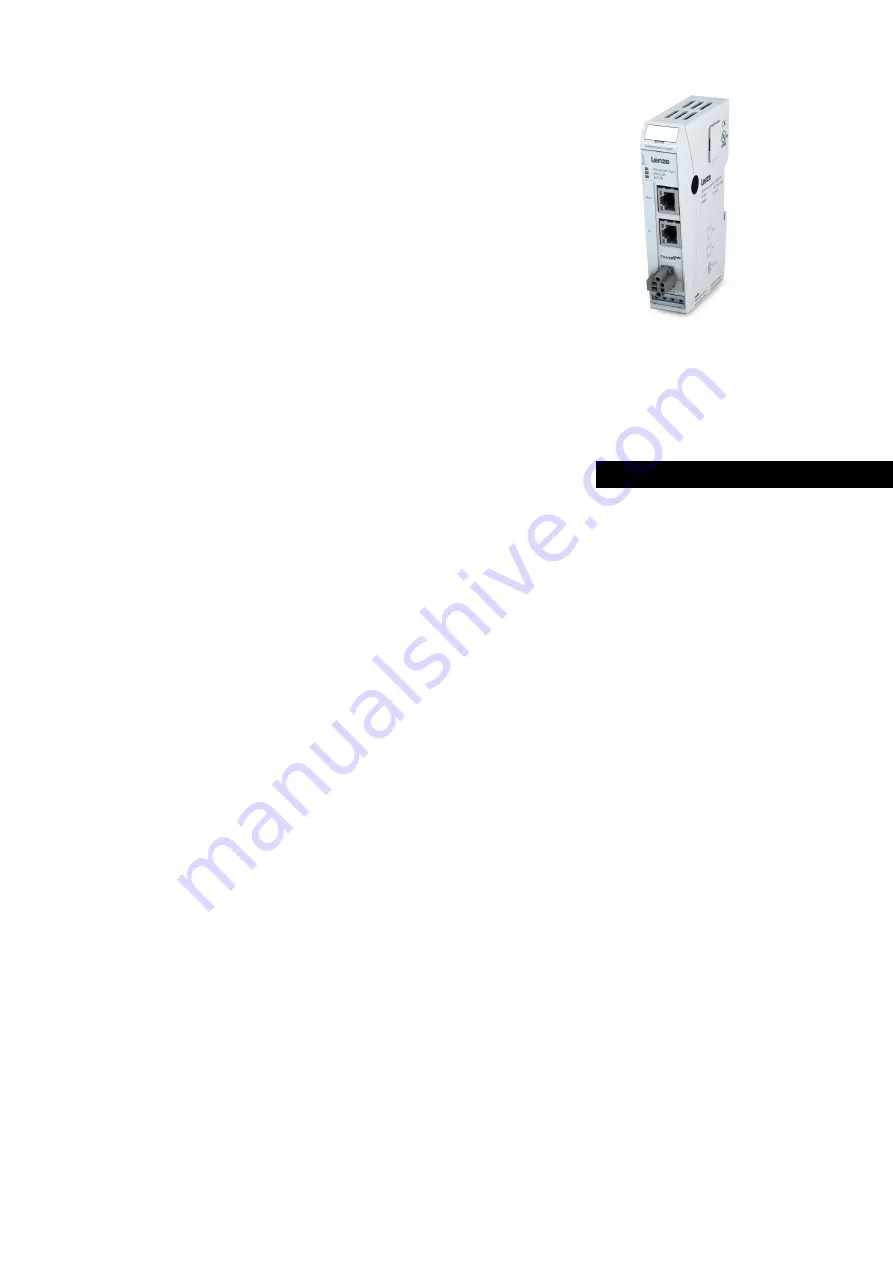
c250−S
C25BAYCB
c250−S Safety bus coupler
l
Page 1: ...URj URj Operating Instructions Translation EN c250 S C25BAYCB c250 S Safety bus coupler l...
Page 2: ......
Page 3: ...stem 10 3 System Description 11 3 1 General conditions of use 11 3 2 Dimensions 11 3 3 Mechanical Design 11 3 3 1 Earth 12 3 3 2 Installation 13 3 4 System Power Supply 16 3 4 1 General 16 3 4 2 Safet...
Page 4: ...ademark and patented technology licenced by Beckhoff Automation GmbH Germany Further information about the PLCopen organisation is available at www plcopen org Title to all companies and company names...
Page 5: ...industrial use They must not be used for any other purposes than the ones specified in the catalogue or the associated technical documentation Proper and safe operation depends on the products being...
Page 6: ...portance Every alert and hazard warning is made up as follows Type and source of risk Potential consequences of non observance Preventive measures DANGER A DANGER warning makes you aware of an immedia...
Page 7: ...creating additional dangers Project Planning 24 VDC power supply generate as electrically safely separated low voltage Suitable devices include split winding transformers built in compliance with Euro...
Page 8: ...e kinds of noise are specified in the applicable product standards IEC 61131 2 which in Europe has been the basis for European Standard EN 61131 2 Information Refer to IEC 61131 4 User s Guideline for...
Page 9: ...in assembly rooms or control cabinets Contamination Use suitable casings to avoid possible negative influences due to humidity corrosive gas liquid or conducting dust Impact and Vibration Consider po...
Page 10: ...er times that conventional fieldbus systems are burdened with 2 2 Lenze Safety System The Lenze Safety System is a system of I O modules for connecting the process signals to an EtherCAT network The L...
Page 11: ...ety bus coupler and the Safety I O modules differ in their connectors and indicators however Figure 2 Module layout The housing mount consists of an aluminum profile with an integral snap on device us...
Page 12: ...housing therefore needs to be suitably connected to an operative earth connector You will normally have to ensure that the connection between module housing and DIN rail conducts well the connection b...
Page 13: ...rd and 35mm to adjacent equipment and control cabinets The lateral distance to external devices and cabinet controls must not fall below 20mm Figure 3 Installation position Installation order in the L...
Page 14: ...mounting of module To interconnect two modules 1 After snapping on the first module to the rail snap on the second module about 1cm away towards the right of the first module 2 Push the second module...
Page 15: ...ngle module 1 Push the module up and against the metal spring located on the underside of the rail guide 2 Tip the module away from the rail as shown in the illustration 3 Pull the module down and out...
Page 16: ...10 Stripping length mm sleeve length mm The Push in spring connector enables fast tool free wire connection by direct plug in technology The stripped solid wires or flexible wires with crimped ferrul...
Page 17: ...and the I O modules It indicates the state of the EtherCAT ASIC State LED flash code Explanation Init Off Initialisierung no data exchange Pre Op Off green 1 1 Pre Operational no data exchange Safe O...
Page 18: ...sections in this manual to know which states of a module are monitored and indicated 3 5 4 LED Power An LED labeled Power is located on every module that has a power supply connector e g for digital...
Page 19: ...nes is automatically closed the effect being did another 100 Base Tx line can be plugged in to connect the next EtherCAT unit to the second bus coupler port You will get the best results concerning di...
Page 20: ...on Connected Green on Connected to Ethernet Traffic Green flashing Exchanging Telegrams 4 1 3 Function see page 19 Module state Variable Data type Explanation Undervoltage BOOL Low voltage supplied po...
Page 21: ...32 digital I Os on every module Supply voltage 24 V DC 20 20 Number of I O modules 20 per bus coupler total max power consumption 3A Electrical insulation modules electrically insulated from one anoth...
Page 22: ...763 Hameln Hans Lenze Str 1 31855 Aerzen GERMANY HR Hannover B 205381 49 5154 82 0 49 5154 82 2800 lenze lenze com www lenze com Lenze Service GmbH Breslauer Stra e 3 32699 Extertal GERMANY 008000 244...