System bus (CAN) with Servo PLC & Drive PLC
General information
2-2
l
PLC-Systembus EN 1.1
2.2
Device identifiers
A so-called node address in the range from 1 to 63 (also called
node ID) is assigned to each
participant part of the system bus network.
•
Each node address may only be assigned once in the network.
2.3
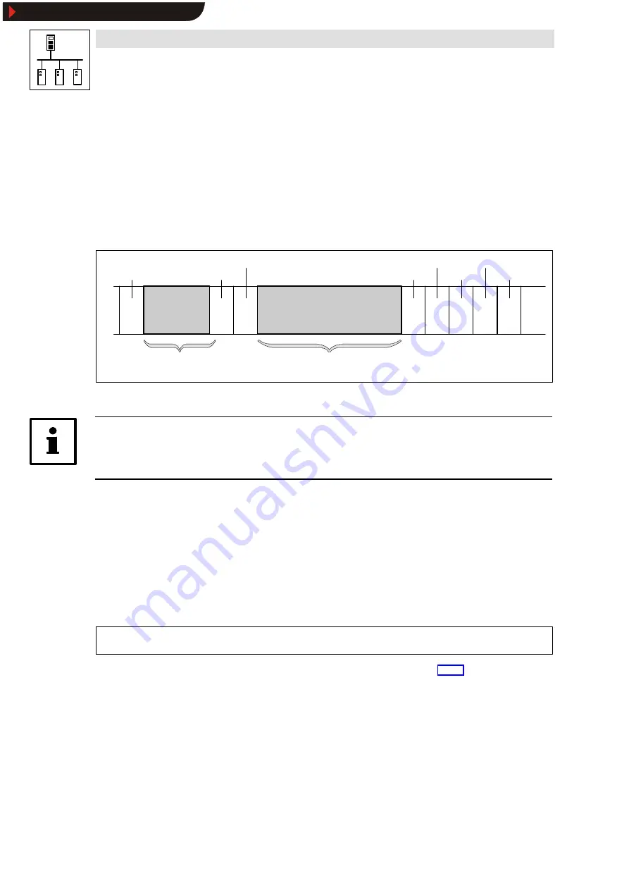
Structure of the CAN telegram
1 bit
11 bits
1 bit
6 bits
0 ... 8 bytes
5 bits
Start
Identifier
RTR bit
Control field
User data
CRC sequence
CRC delimit.
ACK slot
ACK delimit.
End
Description see chapter 2.3.1
•
Network management
•
Parameter data
•
Process data
Description see chapter 2.3.2
1 bit
1 bit
1 bit
7 bits
Fig. 2-1
Basic structure of the CAN telegram
Tip!
The identifier and the user data are important to the user, all other data of the CAN telegram will be
controlled by the system.
2.3.1
Identifier
The CAN communication principle is based on a message-oriented data exchange between a
sender and many receivers. All participants can send and receive messages at the same time.
The
Identifier in the CAN telegram, which is also called COB ID (Communication Object Identifier),
controls which participant is to receive the sent message. Apart from the address, the identifier
includes information about the priority of the message and the type of user data used.
The identifier consists of a ” basic identifier” and the node address of the participant to be addressed:
Identifier
=
Basis-Identifier
+
Knotenadresse
•
With the Lenze devices, the node address is defined in code C0350.
•
For network management and the Sync telegram you only need the basic identifier.
Show/Hide Bookmarks


