background image

Wiring Instructions 

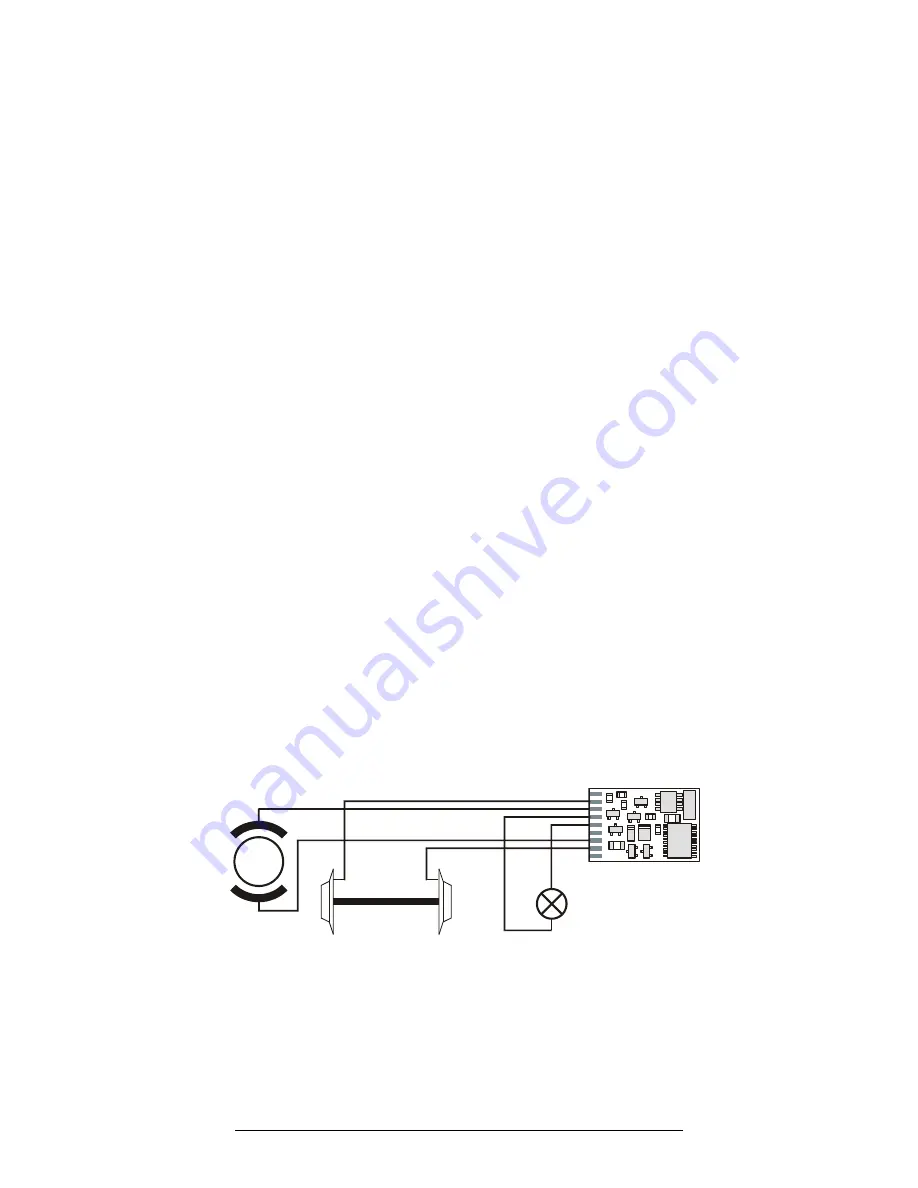
First connect the decoder to the pick-ups from the wheels of the 
locomotive: 

  red cable to the wheels, which in relation to the direction of 

travel, are on the right-hand side of the locomotive  

  black cable to the wheels, which in relation to the direction of 

travel, are on the left-hand side of the locomotive 

Then connect the decoder to the motor connections: 

  orange cable to the motor connection previously connected to 

the right-hand  locomotive wheels 

  grey cable to the motor connection  previously connected to 

the left-hand  locomotive wheels. 

Now connect the function: 

  function output (white cable) to the bulb of the locomotive. 

If the function inside the locomotive (e.g. the bulbs of the light) is  
not electrically connected to the chassis of the locomotive (i.e; if 
they are, "potential free") then connect the other pole of the 
function to the blue  cable, as shown in the illustration. If a 
connection between functions and chassis does exist, then the 
blue cable remains unused. When connected to the blue cable the 
bulbs shine somewhat brighter. Which option you choose depends 
on the design of the locomotive. 
For the connection of LEDs note that the  blue cable is the positive 
pole (anode side of the LED) and the function output the negative 
pole (cathode side of the  LED). The voltage at the function output 
is approximately 16 V. Please do not forget the necessary 
protective resistor. The value of the resistor can be calculated by 
the formula R = V/I where I is current rating of the LED and I is the 
difference between the DCC track voltage and the voltage ratting 
of the LED.  

Motor

Orange

Grey

Red

Black

White

Blue


Wiring the LE1000A


Summary of Contents for DIGITAL plus LE1000W

Page 1: ...DC layouts is possible or can be disabled Provides 1A continuous motor current One function output Function dimming through a selectable second function input Support for Advanced Consist Control and Extended Addressing Support for programming on the mainline Support for all forms of programming as described in NMRA RP 9 2 3 Programmable locomotive address starting speed acceleration brake momentu...

Page 2: ...decoder Instead put insulating tape or something similar around the metal components of the locomotive By doing so you can avoid unintentional short circuits while allowing air to cool the decoder Use double sided adhesive tape to affix the decoder to the locomotive Locomotives equipped with Digital plus decoders must not be run using powered overhead line either on conventional DC control or DCC ...

Page 3: ...sions 23 x 16 x 3 2 mm Installation of the LE1000W Take note of which motor connection is connected to the right hand rail and which to the left hand rail If you do this you will know which wire of the decoder needs to be soldered to which motor connection in order to achieve the desired direction of travel After the removal of the original connections to the motor brushes check to ensure that bot...

Page 4: ...ectrically connected to the chassis of the locomotive i e if they are potential free then connect the other pole of the function to the blue cable as shown in the illustration If a connection between functions and chassis does exist then the blue cable remains unused When connected to the blue cable the bulbs shine somewhat brighter Which option you choose depends on the design of the locomotive F...

Page 5: ...the same even when the track voltage is switched off These settings are called configuration variables or simply CV The configuration of the values is done electronically which means that it is not necessary to open the locomotive again after the decoder has been installed The LE1000 supports all NMRA DCC programming modes and can be programmed by any NMRA DCC programmer With some entry level syst...

Page 6: ...tor in speed step 1 Set this value so that the locomotive just starts moving in speed step 1 1 31 10 3 3 Acceleration Momentum Determines the rate of change of speed upon acceleration A higher value leads to a slower acceleration 1 255 1 4 4 Brake Momentum Determines the rate of change of speed upon braking A higher value leads to longer brake distance 1 255 1 5 Contains CV29 see CV29 below 0 39 6...

Page 7: ...dressing 1 Four digit extended addressing 0 1 0 32 bit 6 bit 7 Not used always 0 0 0 50 Decoder Configuration byte 2 Similar to CV 29 but other properties are set with this byte 0 12 4 bits 0 1 1 2 Not used alwasy 0 0 0 bit 2 3 Brake momentum on DC operation Only active if conventional DC control CV29 2 is disabled CV 29 bit 2 0 0 locomotive proceeds with track voltage dependent speed inside the c...

Page 8: ...ituted at the manufacturers discretion Please include a 2 shipping and handling fee to cover return shipping from an authorized Lenz GmbH warranty center After 90 days and until 10 years after purchase A 10 service charge which includes repair shipping and handling will be placed on each item that has failed due to manufacturer defects and or accidental user installation problems Should the item n...

Reviews: