General checkout
19
This chapter presents the following information:
• “What to do first” on page 20
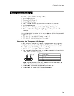
• “Power system checkout” on page 21
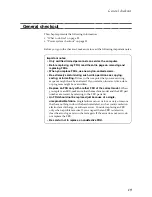
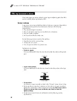
Before you go to the checkout, make sure to read the following important notes:
General checkout
Important notes:
•
Only certified trained personnel can service the computer.
•
Before replacing any FRU, read the entire page on removing and
replacing FRUs.
•
When you replace FRUs, use new nylon-coated screws.
•
Be extremely careful during such write operations as copying,
saving, or formatting.
Drives in the computer that you are servicing
sequence might have been altered. If you select an incorrect drive, data
or programs might be overwritten.
•
Replace an FRU only with another FRU of the correct model.
When
you replace an FRU, make sure that the machine model and the FRU part
number are correct by referring to the FRU parts list.
•
An FRU should not be replaced just because of a single,
unreproducible failure.
Single failures can occur for a variety of reasons
that have nothing to do with a hardware defect, such as cosmic radiation,
electrostatic discharge, or software errors. Consider replacing an FRU
only when a problem recurs. If you suspect that an FRU is defective,
clear the error logs and run the test again. If the error does not recur, do
not replace the FRU.
•
Be careful not to replace a nondefective FRU.
Summary of Contents for YOGA Tablet 2-1371F
Page 1: ...YOGA TABLET 2 with Windows Hardware Maintenance Manual YOGA Tablet 2 1371F ...
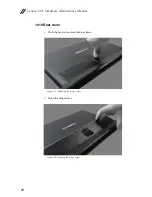
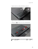
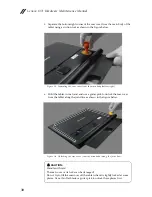
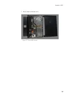
Page 35: ...Lenovo 1371 31 7 Slowly remove the rear cover Figure 1 7 The removed rear cover ...
Page 49: ...Lenovo 1371 45 Figure 3 4 The removed HDMI and audio jack FPC ...
Page 59: ...Lenovo 1371 55 Figure 7 4 The removed main FPC ...
Page 62: ...Lenovo 1371 Hardware Maintenance Manual 58 Figure 8 4 The removed main HDMI FPC ...
Page 65: ...Lenovo 1371 61 Figure 9 4 The removed LCD FPC ...
Page 68: ...Lenovo 1371 Hardware Maintenance Manual 64 Figure 10 3 The removed sub board ...
Page 74: ...Lenovo 1371 Hardware Maintenance Manual 70 Figure 12 4 The removed volume key FPC ...
Page 84: ...Lenovo 1371 Hardware Maintenance Manual 80 Figure 17 4 The removed the front camera ...
Page 87: ...Lenovo 1371 83 Figure 18 4 The removed camera FPC ...
Page 90: ...Lenovo 1371 Hardware Maintenance Manual 86 Figure 19 4 The USB and power key FPC with holder ...
Page 94: ...Lenovo 1371 Hardware Maintenance Manual 90 Figure 20 5 The removed main board ...
Page 96: ...Lenovo 1371 Hardware Maintenance Manual 92 Front view Front camera Microphone Locations ...
Page 99: ...Lenovo 1371 95 ...

