


5. Clear the
Turn on fast startup
check box, and then click
Save changes
.
To disable the built-in battery:
1. Restart your computer. When the logo screen is displayed, immediately press F1 to enter the UEFI BIOS
menu.
2. Select
Config
➙
Power
. The
Power
submenu is displayed.
3. Select
Disable built-in battery
and press Enter.
4. Select
Yes
in the Setup Confirmation window. The built-in battery is disabled and the computer turns off
automatically. Wait three to five minutes to let the computer cool.
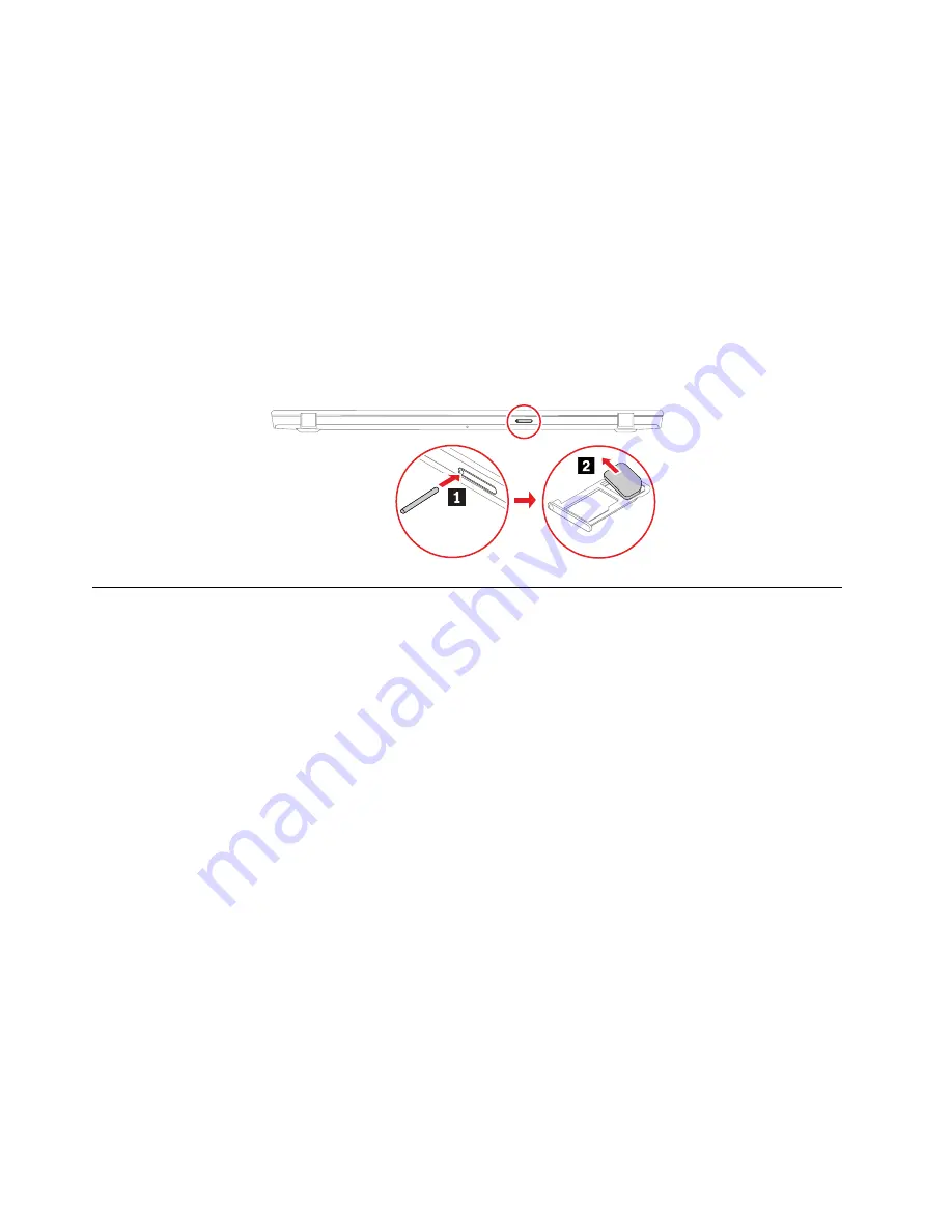
Removing the nano-SIM-card and microSD-card tray
Note:
If the computer you are servicing has a nano-SIM card or microSD card installed, remove the card
with the tray together.
1010 Keyboard (for ThinkPad X13 Gen 1 only)
Removal steps of the keyboard
Notes:
• You might be instructed to slide the keyboard frame forward or backward in some of the following steps.
In this case, ensure that you do not press or hold the keys while sliding the keyboard frame. Otherwise,
the keyboard frame cannot be moved.
• If your replacement keyboard is not shipped with the special tool shown in the following illustrations, you
may use alternative pry tools to remove it.
72
T14s Gen 1 and X13 Gen 1 Hardware Maintenance Manual
Summary of Contents for ThinlPad T14s Gen 1
Page 1: ...T14s Gen 1 and X13 Gen 1 Hardware Maintenance Manual ...
Page 6: ...iv T14s Gen 1 and X13 Gen 1 Hardware Maintenance Manual ...
Page 11: ...DANGER DANGER DANGER DANGER DANGER DANGER Chapter 1 Safety information 5 ...
Page 12: ...DANGER 6 T14s Gen 1 and X13 Gen 1 Hardware Maintenance Manual ...
Page 13: ...PERIGO Chapter 1 Safety information 7 ...
Page 14: ...PERIGO PERIGO PERIGO PERIGO 8 T14s Gen 1 and X13 Gen 1 Hardware Maintenance Manual ...
Page 15: ...PERIGO PERIGO PERIGO DANGER DANGER Chapter 1 Safety information 9 ...
Page 16: ...DANGER DANGER DANGER DANGER DANGER 10 T14s Gen 1 and X13 Gen 1 Hardware Maintenance Manual ...
Page 17: ...DANGER VORSICHT VORSICHT VORSICHT VORSICHT Chapter 1 Safety information 11 ...
Page 18: ...VORSICHT VORSICHT VORSICHT VORSICHT 12 T14s Gen 1 and X13 Gen 1 Hardware Maintenance Manual ...
Page 19: ...Chapter 1 Safety information 13 ...
Page 20: ...14 T14s Gen 1 and X13 Gen 1 Hardware Maintenance Manual ...
Page 21: ...Chapter 1 Safety information 15 ...
Page 22: ...16 T14s Gen 1 and X13 Gen 1 Hardware Maintenance Manual ...
Page 23: ...Chapter 1 Safety information 17 ...
Page 24: ...18 T14s Gen 1 and X13 Gen 1 Hardware Maintenance Manual ...
Page 25: ...Chapter 1 Safety information 19 ...
Page 26: ...20 T14s Gen 1 and X13 Gen 1 Hardware Maintenance Manual ...
Page 30: ...24 T14s Gen 1 and X13 Gen 1 Hardware Maintenance Manual ...
Page 48: ...42 T14s Gen 1 and X13 Gen 1 Hardware Maintenance Manual ...
Page 52: ...46 T14s Gen 1 and X13 Gen 1 Hardware Maintenance Manual ...
Page 59: ...Major FRUs and CRUs ThinkPad T14s Gen 1 a b c d Chapter 6 Locations 53 ...
Page 79: ...a b c d Chapter 8 Removing or replacing a FRU 73 ...
Page 81: ...1020 Base cover assembly Removal steps Chapter 8 Removing or replacing a FRU 75 ...
Page 122: ...116 T14s Gen 1 and X13 Gen 1 Hardware Maintenance Manual ...
Page 123: ......
Page 124: ...Part Number SP40T79957_01 Printed in China 1P P N SP40T79957_01 1PSP40T79957_01 ...