


•
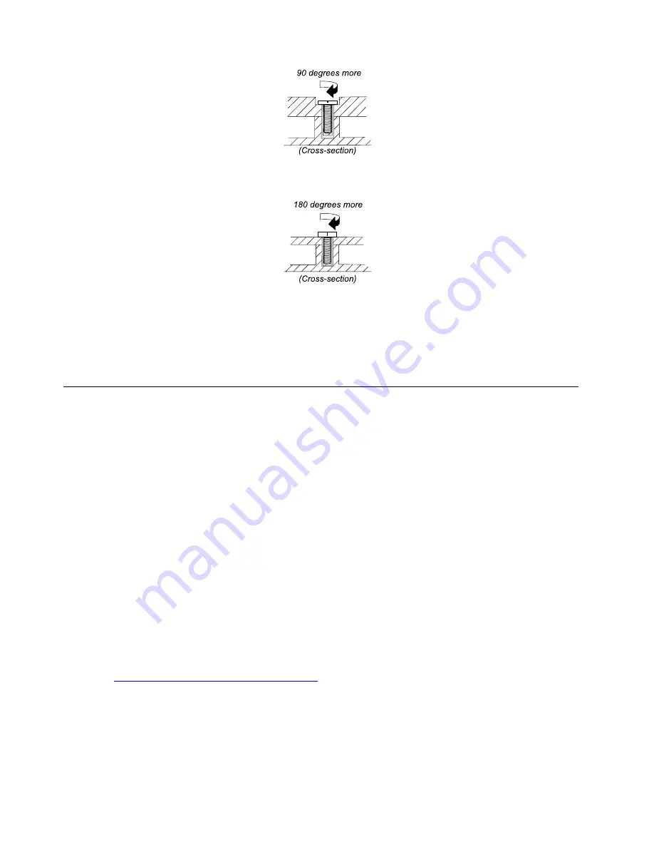
Logic card to plastic
Turn an additional angle of 180 degrees after the screw head touches the surface of the logic card.
Notes:
• Ensure that you use the correct screw. It is recommended to use new screws for replacements. If you
have a torque screwdriver, tighten all screws firmly to the torque specified in the screw information table
for each step.
• Ensure torque screwdrivers are calibrated correctly following country specifications.
Retaining serial numbers
This topic provides instructions on the following:
• “Restoring the serial number of the system unit” on page 68
• “Retaining the UUID” on page 69
Restoring the serial number of the system unit
When the computer was manufactured, the EEPROM on the system board was loaded with the serial
numbers of the system and all major components. These numbers need to remain the same throughout the
life of the computer.
If you replace the system board, you must restore the serial number of the system unit to its original value.
The serial number of the system unit is written on the label attached to the bottom of the computer.
If you cannot find the serial number of the system unit on the bottom of the computer, try the following
method to get the number:
Note:
For Intel models, before you perform the operation, ensure that the UEFI/Legacy setting within the
Startup
menu in the ThinkPad Setup program is set to
UEFI Only
.
1. Connect a USB memory key to the computer.
2. Go to
https://www.lenovo.com/maintenanceutilities
and follow the instructions on the screen to create a
Maintenance Key.
Note:
Only an authorized Lenovo service technician can access the above Web site.
3. Restart the computer.
4. When the logo is displayed, press Esc. The ThinkPad Config Information Update Utility interface is
displayed.
68
T14s Gen 1 and X13 Gen 1 Hardware Maintenance Manual
Summary of Contents for ThinlPad T14s Gen 1
Page 1: ...T14s Gen 1 and X13 Gen 1 Hardware Maintenance Manual ...
Page 6: ...iv T14s Gen 1 and X13 Gen 1 Hardware Maintenance Manual ...
Page 11: ...DANGER DANGER DANGER DANGER DANGER DANGER Chapter 1 Safety information 5 ...
Page 12: ...DANGER 6 T14s Gen 1 and X13 Gen 1 Hardware Maintenance Manual ...
Page 13: ...PERIGO Chapter 1 Safety information 7 ...
Page 14: ...PERIGO PERIGO PERIGO PERIGO 8 T14s Gen 1 and X13 Gen 1 Hardware Maintenance Manual ...
Page 15: ...PERIGO PERIGO PERIGO DANGER DANGER Chapter 1 Safety information 9 ...
Page 16: ...DANGER DANGER DANGER DANGER DANGER 10 T14s Gen 1 and X13 Gen 1 Hardware Maintenance Manual ...
Page 17: ...DANGER VORSICHT VORSICHT VORSICHT VORSICHT Chapter 1 Safety information 11 ...
Page 18: ...VORSICHT VORSICHT VORSICHT VORSICHT 12 T14s Gen 1 and X13 Gen 1 Hardware Maintenance Manual ...
Page 19: ...Chapter 1 Safety information 13 ...
Page 20: ...14 T14s Gen 1 and X13 Gen 1 Hardware Maintenance Manual ...
Page 21: ...Chapter 1 Safety information 15 ...
Page 22: ...16 T14s Gen 1 and X13 Gen 1 Hardware Maintenance Manual ...
Page 23: ...Chapter 1 Safety information 17 ...
Page 24: ...18 T14s Gen 1 and X13 Gen 1 Hardware Maintenance Manual ...
Page 25: ...Chapter 1 Safety information 19 ...
Page 26: ...20 T14s Gen 1 and X13 Gen 1 Hardware Maintenance Manual ...
Page 30: ...24 T14s Gen 1 and X13 Gen 1 Hardware Maintenance Manual ...
Page 48: ...42 T14s Gen 1 and X13 Gen 1 Hardware Maintenance Manual ...
Page 52: ...46 T14s Gen 1 and X13 Gen 1 Hardware Maintenance Manual ...
Page 59: ...Major FRUs and CRUs ThinkPad T14s Gen 1 a b c d Chapter 6 Locations 53 ...
Page 79: ...a b c d Chapter 8 Removing or replacing a FRU 73 ...
Page 81: ...1020 Base cover assembly Removal steps Chapter 8 Removing or replacing a FRU 75 ...
Page 122: ...116 T14s Gen 1 and X13 Gen 1 Hardware Maintenance Manual ...
Page 123: ......
Page 124: ...Part Number SP40T79957_01 Printed in China 1P P N SP40T79957_01 1PSP40T79957_01 ...