


For other models:
1
2
2
10
12
11
13
14
15
16
3
3
4
5
6
7
8
9
1
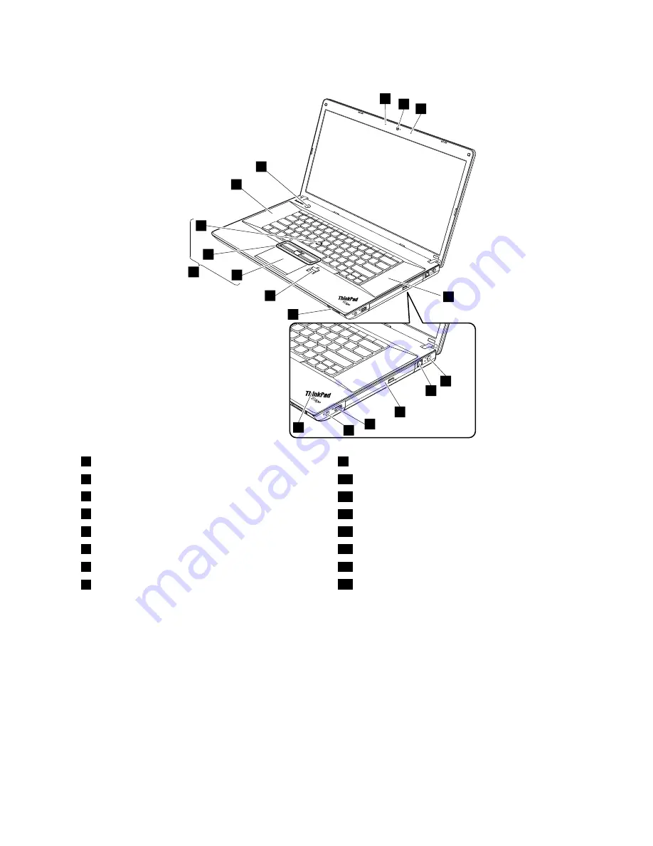
Integrated camera
9
System status indicator
1
2
Built-in microphones
10
Media card reader slot
3
Built-in stereo speakers
11
Fingerprint reader (on some models)
4
ac power connector
12
Touch pad
5
RJ45 Ethernet connector
13
TrackPoint buttons
6
Optical drive or blank bezel
14
TrackPoint pointing stick
7
Always On USB connector
15
UltraNav pointing device
8
Combo audio jack
16
Power button
1
: For the description of the system status indicator, see Chapter 5 “Status indicators” on page 43.
Chapter 7
.
Locations
49
Summary of Contents for ThinkPad Edge E530
Page 1: ...Hardware Maintenance Manual ThinkPad Edge E530 E530c and E535 ...
Page 6: ...iv Hardware Maintenance Manual ...
Page 11: ...DANGER DANGER DANGER DANGER DANGER DANGER Chapter 1 Safety information 5 ...
Page 12: ...DANGER 6 Hardware Maintenance Manual ...
Page 13: ...PERIGO PERIGO PERIGO Chapter 1 Safety information 7 ...
Page 14: ...PERIGO PERIGO PERIGO PERIGO PERIGO 8 Hardware Maintenance Manual ...
Page 15: ...DANGER DANGER DANGER DANGER DANGER Chapter 1 Safety information 9 ...
Page 16: ...DANGER DANGER DANGER VORSICHT VORSICHT 10 Hardware Maintenance Manual ...
Page 17: ...VORSICHT VORSICHT VORSICHT VORSICHT VORSICHT VORSICHT Chapter 1 Safety information 11 ...
Page 18: ...12 Hardware Maintenance Manual ...
Page 19: ...Chapter 1 Safety information 13 ...
Page 20: ...14 Hardware Maintenance Manual ...
Page 21: ...Chapter 1 Safety information 15 ...
Page 22: ...16 Hardware Maintenance Manual ...
Page 24: ...18 Hardware Maintenance Manual ...
Page 25: ...Chapter 1 Safety information 19 ...
Page 26: ...20 Hardware Maintenance Manual ...
Page 27: ...Chapter 1 Safety information 21 ...
Page 28: ...22 Hardware Maintenance Manual ...
Page 48: ...42 Hardware Maintenance Manual ...
Page 62: ...56 Hardware Maintenance Manual ...
Page 114: ...108 Hardware Maintenance Manual ...
Page 117: ......
Page 118: ...Part Number 0B48439_01 Printed in China 1P P N 0B48439_01 1P0B48439_01 ...


