


Figure
11
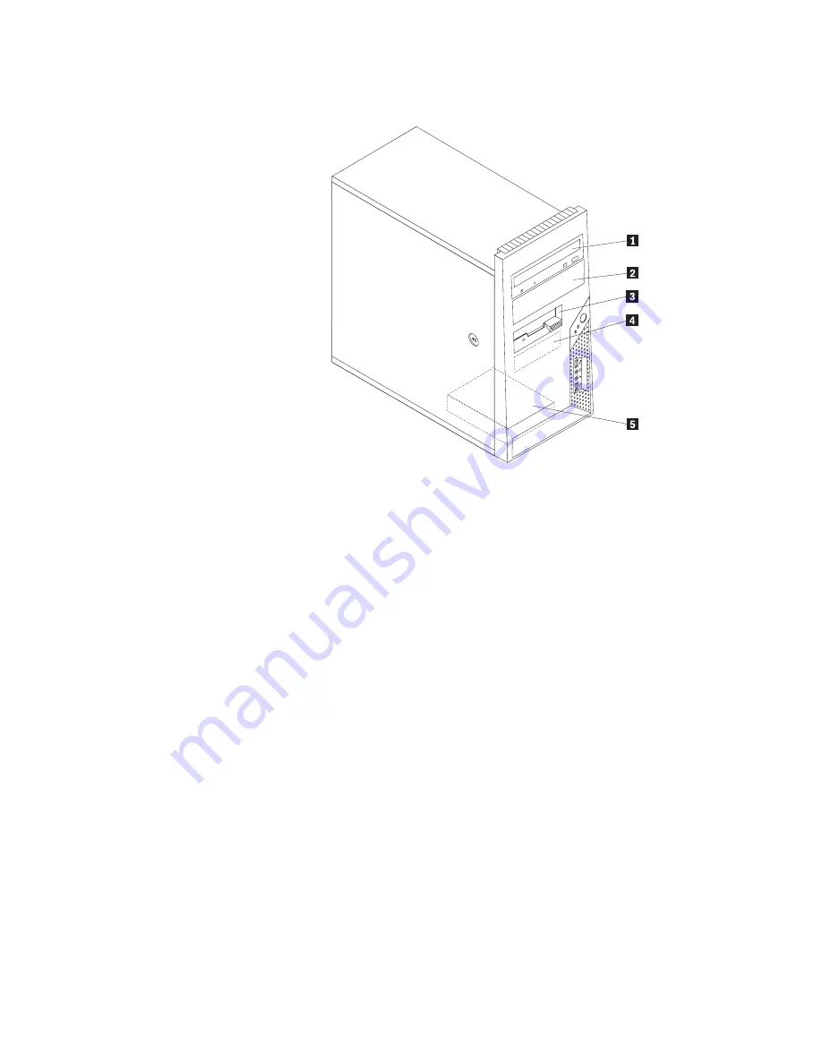
shows
the
location
of
the
drive
bays.
The
following
list
describes
the
types
and
size
of
drives
that
you
can
install
in
each
bay:
1
Bay
1
-
Maximum
height:
43.0
mm
(1.7
in.)
v
Optical
drive
such
as
CD
drive
or
DVD
drive
(preinstalled
in
some
models)
v
5.25-inch
hard
disk
drive
v
3.5-inch
hard
disk
drive
(requires
a
Universal
Adapter
Bracket,
5.25
to
3.5-inch)*
2
Bay
2
-
Maximum
height:
43.0
mm
(1.7
in.)
v
Optical
drive
such
as
CD
drive
or
DVD
drive
v
5.25-inch
removable
media
drive
v
3.5-inch
hard
disk
drive
(requires
a
Universal
Adapter
Bracket,
5.25
to
3.5-inch)*
3
Bay
3
-
Maximum
height:
25.8
mm
(1.0
in.)
3.5-inch
diskette
drive
(some
models
preinstalled)
4
Bay
4
-
Maximum
height:
25.8
mm
(1.0
in.)
3.5-inch
SATA
hard
disk
drive
(preinstalled)
5
Bay
5
-
Maximum
height:
25.8
mm
(1.0
in.)
3.5-inch
SATA
hard
disk
drive
*
You
can
obtain
a
Universal
Adapter
Bracket,
5.25
to
3.5-inch
from
a
local
computer
retailer
or
by
contacting
the
Customer
Support
Center.
Installing
a
drive
in
bay
1
or
bay
2
This
section
provides
instructions
on
how
to
install
a
drive
in
bay
1
or
bay
2.
1.
Remove
the
computer
cover.
See
“Removing
the
cover”
on
page
11.
Figure
11.
Drive
bay
locations
Chapter
3.
Installing
options
and
replacing
hardware
19
Summary of Contents for THINKCENTRE 9120
Page 2: ......
Page 3: ...ThinkCentre Hardware Installation and Replacement Guide ...
Page 6: ...iv Hardware Installation and Replacement Guide ...
Page 8: ...vi Hardware Installation and Replacement Guide ...
Page 10: ...2 Hardware Installation and Replacement Guide ...
Page 18: ...10 Hardware Installation and Replacement Guide ...
Page 50: ...42 Hardware Installation and Replacement Guide ...
Page 56: ...48 Hardware Installation and Replacement Guide ...
Page 61: ......
Page 62: ...Part Number 43C4834 Printed in USA 1P P N 43C4834 ...