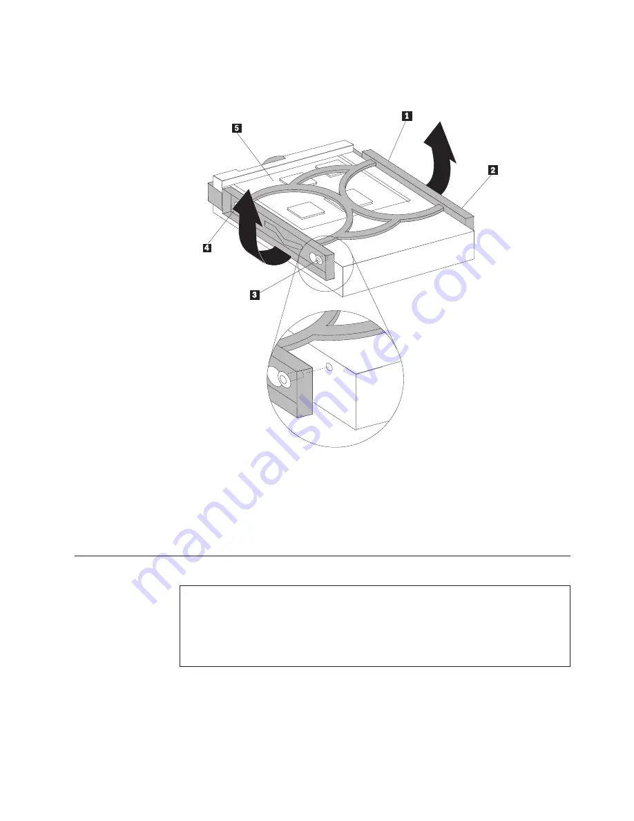
Lenovo ThinkCentre 8099 Hardware Replacement Manual Download Page 31

7.


Install


the


new


drive


into


the


blue


bracket,


flex


the


bracket,


and


align


the


pins


1


through


4

on


the


bracket


with


the


holes


in


the


hard


disk


drive.


Do


not


touch


the


circuit


board


5


on


the


bottom


of


the


hard


disk


drive.


8.


Insert


the


new


hard


disk


drive


and


bracket


into


the


hard


disk


drive


bay


and


snap


into


position.


9.


Pivot


the


drive


and


bracket


towards


the


front


of


the


computer


and


snap


it


into


position.


10.


Connect


the


signal


and


power


cables


to


the


drive.


11.


Go


to


“Completing


the


CRU


replacement”


on


page


28.

Replacing


an


optical


drive


Attention


Do


not


open


your


computer


or


attempt


any


repair


before


reading


the


“Important


safety


information”


in


the


Quick


Reference


that


was


included


with


your


computer


or


in


the


Hardware


Maintenance


Manual


(HMM)


for


the


computer.


To


obtain


copies


of


the


Quick


Reference


or


the


HMM

,


go


to


the


Support


Web


site


at


http://www.lenovo.com/think/support.


To


replace


the


optical


drive:


1.


Open


the


computer


cover.


See


“Opening


the


cover”


on


page


5.


Chapter


2.


Replacing


hardware


23

Summary of Contents for ThinkCentre 8099

Page 1: ...Hardware Replacement Guide Types 8099 8116 8155 8156 Types 8157 8158 8159 8160 Types 8215 9210 9211 ...

Page 2: ......

Page 3: ...Hardware Replacement Guide Types 8099 8116 8155 8156 Types 8157 8158 8159 8160 Types 8215 9210 9211 ...

Page 4: ...se duplication or disclosure by the Government is subject to the GSA ADP Schedule contract with Lenovo Group Limited if any or the standard terms of this commercial license or if the agency is unable to accept this Program under these terms then we provide this Program under the provisions set forth in Commercial Computer Software Restricted Rights at FAR 52 227 19 when applicable or under Rights ...

Page 5: ...stem board 4 Chapter 2 Replacing hardware 5 Opening the cover 5 Replacing the power supply 6 Replacing the system board assembly 8 Replacing the microprocessor 12 Replacing a memory module 17 Replacing an adapter 19 Replacing a hard disk drive 21 Replacing an optical drive 23 Replacing the diskette drive 25 Replacing the keyboard 26 Replacing the mouse 26 Replacing the internal speaker 27 Completi...

Page 6: ...iv Hardware Replacement Guide ...

Page 7: ...speaker Safety information for replacing CRUs Do not open your computer or attempt any repair before reading the Important safety information in the Quick Reference that was included with your computer If you no longer have this copy of the Quick Reference you can obtain one online from the Support Web site at http www lenovo com think support Safety information for replacing FRUs Do not attempt a...

Page 8: ...amage v Limit your movement Movement can cause static electricity to build up around you v Always handle parts and other computer components carefully Handle adapters memory modules system boards and microprocessors by the edges Never touch any exposed circuitry v Prevent others from touching the parts and other computer components v Before you replace a new part touch the static protective packag...

Page 9: ...ge 5 Locating components The following illustration will help you locate the various components in your computer 1 Diskette drive lock 7 Internal speaker 2 Microprocessor and heat sink 8 Hard disk drive 3 Memory connectors 2 9 Optical drive such as a CD or DVD drive 4 Battery 10 Optical drive lock 5 PCI riser assembly 11 Diskette drive 6 Power supply Lenovo 2005 Portions IBM Corp 2005 1 ...

Page 10: ...ont of your computer Note Not all computer models will have the following controls and connections 1 Optical drive or second hard disk drive some models 5 USB connectors 2 2 Hard disk drive activity indicator 6 Microphone connector 3 Power on indicator 7 Headphone connector 4 Power button 8 Diskette drive some models 2 Hardware Replacement Guide ...

Page 11: ...onnector 2 Cable lock Kensington latch 10 Audio line in connector 3 PCI Express x1 adapter connector 11 Audio line out connector 4 PCI adapter connector 12 USB connectors 4 5 Serial connectors 2 13 Standard keyboard connector 6 Ethernet connector 14 Standard mouse connector 7 USB connectors 2 15 Power supply diagnostic LEDs 8 VGA monitor connector Chapter 1 Locations 3 ...

Page 12: ...nector 2 Memory connector 2 10 Front panel connector 3 SATA IDE connectors 2 11 Power supply connector 4 Chassis intrusion switch 12 PATA primary IDE connector 5 PCI riser connector 13 12V Power connector 6 Battery 14 Microprocessor 7 Clear CMOS Recovery jumper 15 Fan connector 2 8 Internal speaker connector 16 Fan connector 1 4 Hardware Replacement Guide ...

Page 13: ...over To open the computer cover 1 Remove any media diskettes CDs or tapes from the drives shut down your operating system turn off all attached devices and the computer 2 Unplug all power cords from electrical outlets 3 Disconnect the cables attached to the computer This includes power cords input output I O cables and any other cables that are connected to the computer See Locating controls and c...

Page 14: ...upport Web site at http www lenovo com think support To replace the power supply 1 Remove the screws at the rear of the chassis that secure the power supply 2 Open the computer cover See the Opening the cover on page 5 3 Pivot the drive bay assembly upward to gain access to the cable connections 4 Locate the power supply See Locating components on page 1 Important Note the cable routing It is impo...

Page 15: ...from the computer 9 Install the new power supply into the chassis so that the screw holes in the power supply assembly align with those in the chassis Note Use only the screws provided by Lenovo 10 Install and tighten the assembly screws into the rear of the chassis 11 Reconnect the power supply connectors to the hard disk drive and optical drive 12 Reconnect the power supply cables to the system ...

Page 16: ...e Maintenance Manual HMM for the computer To obtain copies of the Quick Reference or the HMM go to the Support Web site at http www lenovo com think support To replace the system board assembly 1 Turn off the computer and allow the computer to cool for one hour 2 Open the computer cover See Opening the cover on page 5 3 Pivot the drive bay assembly upward to gain access to the system board 8 Hardw...

Page 17: ...y installed 5 Disconnect the cables connected to the system board See Identifying parts on the system board on page 4 Important Note the cable routing It is important to route the cables the same way after you install the new system board 6 Using the two blue handles provided lift the system board assembly out of the computer Chapter 2 Replacing hardware 9 ...

Page 18: ...efective system board next to the new system board on a clean flat surface 8 Release the lever 1 holding the microprocessor heat sink 9 Remove the heat sink from the system board 10 Release the lever 1 for the microprocessor retainer 2 securing the microprocessor 3 and pivot the retainer upward to the open position XXXXXXXXX 10 Hardware Replacement Guide ...

Page 19: ...croprocessor on the new system board X X X X X X X X X b Do not drop anything on the socket while it is open Keep all contacts as clean as possible 12 On the new system board release the lever securing the microprocessor retainer and then pivot the retainer until it is fully open 13 Position the microprocessor so that the notches on the microprocessor are aligned with the tabs in the microprocesso...

Page 20: ...e system board with the slots in the rear of the computer chassis Slide the system board toward the rear of the chassis 19 Reconnect the cables that were disconnected from the system board Make sure all cables are routed correctly See Identifying parts on the system board on page 4 20 Reinstall the PCI riser assembly and adapters 21 Go to Completing the CRU replacement on page 28 Replacing the mic...

Page 21: ... overheat causing intermittent problems Important Do not touch the gold contacts on the bottom of the microprocessor Use the vacuum pen provided to remove and install the microprocessor If you must touch the microprocessor touch only the sides To replace the microprocessor 1 Open the computer cover See Opening the cover on page 5 2 Pivot the drive bay assembly upward to gain access to the micropro...

Page 22: ...heat sink with the a new microprocessor If you use the old heat sink with the new microprocessor your computer might overheat causing intermittent problems 5 Release the lever 1 for the microprocessor retainer 2 securing the microprocessor 3 and pivot the retainer upward until it is fully open XXXXXXXXX 14 Hardware Replacement Guide ...

Page 23: ...icroprocessor touch only the sides a Note the orientation of the notches 1 on the microprocessor This is important when reinstalling the microprocessor on the system board X X X X X X X X X b Do not drop anything on the socket while it is open Keep all contacts as clean as possible 7 Make sure that the lever on the microprocessor retainer is fully open Chapter 2 Replacing hardware 15 ...

Page 24: ...the microprocessor so that the notches on the microprocessor are aligned with the tabs in the microprocessor socket Important To avoid damaging the microprocessor contacts do not tilt the microprocessor when installing it into the socket 10 Use the vacuum pen 1 to lower the microprocessor straight down into the microprocessor socket 11 Lower the microprocessor retainer and lower the lever to secur...

Page 25: ...any repair before reading the Important safety information in the Quick Reference that was included with your computer or in the Hardware Maintenance Manual HMM for the computer To obtain copies of the Quick Reference or the HMM go to the Support Web site at http www lenovo com think support To replace the memory modules 1 Open the computer cover See Opening the cover on page 5 Chapter 2 Replacing...

Page 26: ...dle provided to remove the PCI riser assembly and any adapters that are currently installed 3 Pivot the drive bay assembly upward to gain access to the memory module 4 Locate the memory connectors See Identifying parts on the system board on page 4 18 Hardware Replacement Guide ...

Page 27: ...e PCI riser assembly and adapters 8 Go to Completing the CRU replacement on page 28 Replacing an adapter Attention Do not open your computer or attempt any repair before reading the Important safety information in the Quick Reference that was included with your computer or in the Hardware Maintenance Manual HMM for the computer To obtain copies of the Quick Reference or the HMM go to the Support W...

Page 28: ... are already installed 3 Pivot the adapter latch to release the adapter 4 Remove the adapter being replaced from the PCI riser 5 Remove the new adapter from its static protective package 6 Install the new adapter into the appropriate connector into the PCI riser 7 Ensure the adapter is fully seated into the adapter connector 20 Hardware Replacement Guide ...

Page 29: ...ry CDs The set of Product Recovery CDs will enable you to restore the contents of the hard disk to the same state as when your computer was originally shipped from the factory For more information on recovering factory installed software refer to Recovering software in your Quick Reference To replace the hard disk drive 1 Open the computer cover See Opening the cover on page 5 2 Pivot the drive ba...

Page 30: ...6 Remove the defective hard disk drive from the bracket by flexing the bracket Note Make sure you notice the orientation of the hard disk drive in the blue bracket 22 Hardware Replacement Guide ...

Page 31: ...position 10 Connect the signal and power cables to the drive 11 Go to Completing the CRU replacement on page 28 Replacing an optical drive Attention Do not open your computer or attempt any repair before reading the Important safety information in the Quick Reference that was included with your computer or in the Hardware Maintenance Manual HMM for the computer To obtain copies of the Quick Refere...

Page 32: ...or at the front of the optical drive and slide it out the front of the computer 6 Install the new optical drive into the bay 7 Slide the optical drive lock to the locked position 8 Place the master slave jumper on the drive in the same position as on the drive being replaced 9 Connect the signal and power cables to the rear of the optical drive 10 Go to Completing the CRU replacement on page 28 24...

Page 33: ...rt To replace the diskette drive 1 Open the computer cover See Opening the cover on page 5 2 Slide the diskette drive lock 1 to the unlocked position 3 Pivot the drive bay assembly upward to give access to the diskette drive 4 Slide the drive towards the rear of the computer and remove the drive 5 Disconnect the flat cable from the failing drive 6 Connect the flat cable to the new drive 7 Install ...

Page 34: ... on page 2 Note Your keyboard might be connected to the standard keyboard connector 1 at the rear of the computer or to a USB connector 2 at either the front or rear of the computer 4 Disconnect the failing keyboard cable from the computer and connect the new keyboard cable to the same connector 5 Go to Completing the CRU replacement on page 28 Replacing the mouse Attention Do not open your comput...

Page 35: ... to the connector 6 Go to Completing the CRU replacement on page 28 Replacing the internal speaker Attention Do not open your computer or attempt any repair before reading the Important safety information in the Quick Reference that was included with your computer or in the Hardware Maintenance Manual HMM for the computer To obtain copies of the Quick Reference or the HMM go to the Support Web sit...

Page 36: ... system board See Identifying parts on the system board on page 4 8 Go to Completing the CRU replacement Completing the CRU replacement After replacing the parts you need to close the cover and reconnect cables including telephone lines and power cords Also depending on the part that was replaced you might need to confirm the updated information in the Setup Utility program See Starting the Setup ...

Page 37: ...ost areas of the world Lenovo requires the return of the defective CRU Information about this will come with the CRU or will come a few days after the CRU arrives Updating flashing BIOS from a diskette or CD ROM Important Start the Setup Utility program to view your system information See Starting the Setup Utility in your Quick Reference or the Hardware Maintenance Manual If the serial number and...

Page 38: ... change the serial number press Y 5 Type in the seven character serial number of your computer and then press Enter 6 When prompted to change the machine type model press Y 7 Type in the seven character machine type model of your computer and then press Enter 8 Follow the instructions on the screen to complete the update 30 Hardware Replacement Guide ...

Page 39: ...his information could include technical inaccuracies or typographical errors Changes are periodically made to the information herein these changes will be incorporated in new editions of the publication Lenovo may make improvements and or changes in the product s and or the program s described in this publication at any time without notice The products described in this document are not intended f...

Page 40: ...hat is protected by method claims of certain U S patents and other intellectual property rights owned by Macrovision Corporation and other rights owners Use of this copyright protection technology must be authorized by Macrovision Corporation and is intended for home and other limited viewing uses only unless otherwise authorized by Macrovision Corporation Reverse engineering or disassembly is pro...

Page 41: ......

Page 42: ...Part Number 39J8231 Printed in USA 1P P N 39J8231 ...

Reviews: