


Drive LED
Status
Description
8
Drive status LED (right)
Solid yellow
The drive has an error.
Blinking yellow (blinking slowly, about one
flash per second)
The drive is being rebuilt.
Blinking yellow (blinking rapidly, about four
flashes per second)
The RAID adapter is locating the drive.
9
Drive activity LED (left)
Solid green
The drive is powered but not active.
Blinking green
The drive is active.
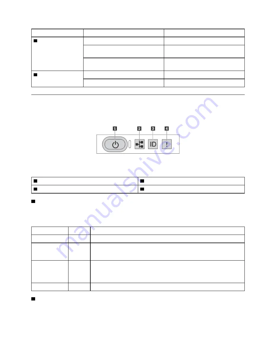
Operator information panel
The operator information panel of the server provides controls and LEDs.
The following illustration shows the operator information panel of the server.
Figure 7. Operator information panel
Table 3. Components on the operator information panel
1
Power button with power status LED
2
Network activity LED
3
System ID button with system ID LED
4
System error LED
1
Power button with power status LED
You can press the power button to power on the server when you finish setting up the server. You also can
hold the power button for several seconds to power off the server if you cannot shut down the server from
the operating system. The power status LED helps you to determine the current power status.
Status
Color
Description
Solid on
Green
The server is on and running.
Slow blinking
(about one flash
per second)
Green
The server is off and is ready to be powered on (standby state).
Fast blinking
(about four
flashes per
second)
Green
The server is off, but the XClarity Controller is initializing, and the server is not ready
to be powered on.
Off
None
There is no ac power applied to the server.
2
Network activity LED
The network activity LED on the operator information panel helps you identify the network connectivity and
activity.
.
15
Summary of Contents for ThinkAgile MX3321-F
Page 1: ...ThinkAgile MX Certified Node 1U ThinkAgile MX3321 H MX3321 F User Guide Machine Type 7D1H ...
Page 32: ...28 ThinkAgile MX Certified Node 1UThinkAgile MX3321 H MX3321 FUser Guide ...
Page 118: ...114 ThinkAgile MX Certified Node 1UThinkAgile MX3321 H MX3321 FUser Guide ...
Page 125: ......
Page 126: ......


