


© Copyright Lenovo 2015
Chapter 2: Switch Components
21
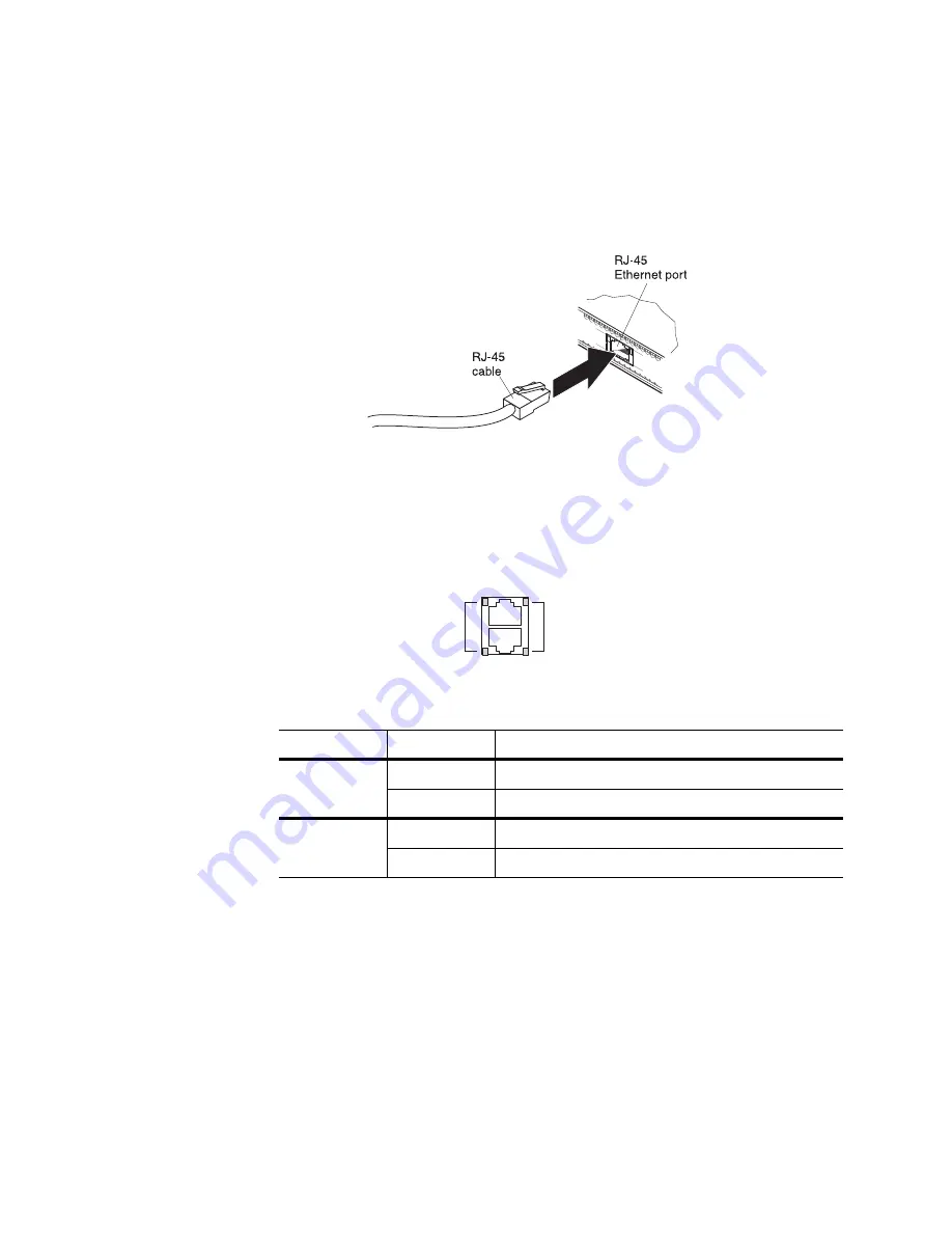
RJ-45 Management Ports
There are two RJ-45 management ports on the front panel of the switch. Each
supports 10/100/1000BASE-T, in-line switch management.
To attach an RJ-45 connector to the switch, push the RJ-45 cable connector into the
port connector until it clicks into place.
To disconnect the RJ-45 cable, squeeze the release tab and gently pull the cable
connector out of the switch connector.
RJ-45 Management LEDs
The RJ-45 management port LEDs are oriented as shown in the following figure.
Figure 5. RJ-45 management port LEDs
Status LEDs for the RJ-45 management port are described in the following table.
Reset Button
The Reset button is recessed within a hole on the front panel. Use a straightened
paper clip or similar object to press the Reset button. The Reset button allows
technicians to reset the switch as follows:
•
Normal reset—Press and release Reset. The switch resets and reloads the
configuration files.
•
Factory reset—Press and hold Reset for more than five seconds. The switch
resets and reverts all configuration settings to the factory defaults.
Table 3. RJ-45 status LEDs behavior
LED
State
Functional Meaning
Link
Steady green
Link up
Off
No link
Activity
Flashing green
Activity
Off
No activity
Link LEDs
Activity LEDs
Summary of Contents for RackSwitch G8124E
Page 1: ...Lenovo RackSwitch G8124 E Installation Guide ...
Page 6: ...6 G8124 E Installation Guide ...
Page 14: ...14 G8124 E Installation Guide ...
Page 18: ...18 G8124 E Installation Guide ...
Page 64: ...64 G8124 E Installation Guide ...
Page 66: ...66 G8124 E Installation Guide ...
Page 78: ...78 G8124 E Installation Guide ...


