


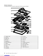
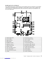


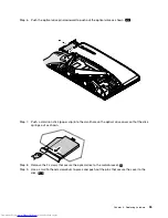
Chapter 7. Locating connectors, controls and components
This section provides illustrations to help locate the various connectors, controls and components of the
computer.
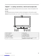
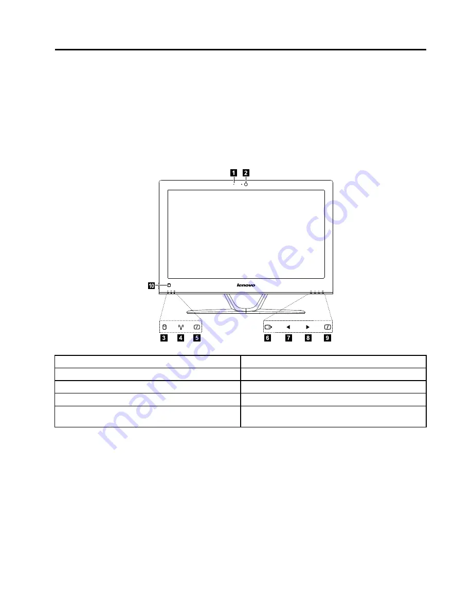
Font view
The following illustration shows the location of controls and components on the front of the computer.
Attention:
Be careful not to block any air vents on the computer. Blocked air vents can cause overheating.
1
2
3
7
6
5
4
8
9
1
0
1. Built-in microphone
6. Menu button
2. Built-in camera
7. Left direction button
3. Hard disk drive indicator
8. Right direction button
4. Wi-Fi status indicator
9. Monitor On/Off button
5. Monitor On/Off indicator
10. Built-in IR receiver (Only functional on models
equipped with a IR receiver module)
© Copyright Lenovo 2012
21
Summary of Contents for IdeaCentre C540
Page 1: ...Lenovo C540 Hardware Maintenance Manual ideaideaideaCentreidea Machine Types 10110 6267 C540 ...
Page 2: ......
Page 3: ...Lenovo C540 Hardware Maintenance Manual Machine Types 10110 6267 C540 ...
Page 6: ...iv Lenovo C540Hardware Maintenance Manual ...
Page 8: ...2 Lenovo C540Hardware Maintenance Manual ...
Page 16: ...10 Lenovo C540Hardware Maintenance Manual ...
Page 18: ...12 Lenovo C540Hardware Maintenance Manual ...
Page 24: ...18 Lenovo C540Hardware Maintenance Manual ...
Page 32: ...26 Lenovo C540Hardware Maintenance Manual ...
Page 62: ...56 Lenovo C540Hardware Maintenance Manual ...