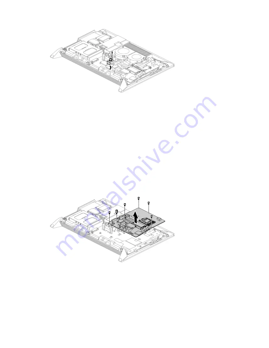
Step 17. Remove all the cables connected to the motherboard, including:
a.
LVDS cable
b.
Hard disk drive power and SATA cables.
c.
Optical disk drive power and SATA cables.
d.
Power supply cables
e.
Converter cable
f.
Speaker cable
g.
Camera cable
h.
Power board cable
i.
Front function board cable
j.
Front indicator board cable
k.
B-CAS card cable
Step 18. Remove the seven screws that secure the motherboard to the chassis and lift up the motherboard
as shown.
Step 19. To install the new motherboard:
a.
Line up the motherboard with the chassis, then secure it with the seven screws.
b.
Insert the notched end of the TV-Tuner card into the card port on the new motherboard and
secure it with the screw.
c.
Insert the notched end of the Wi-Fi card into the card port on the new motherboard and
secure it with the screw.
d.
Install the CPU to the new motherboard and secure the CPU in the socket, close the CPU
retainer and lock it into position with the small handle.
Chapter 8
.
Replacing hardware
49
Summary of Contents for IdeaCentre B350
Page 1: ...IdeaCentre B350 B355 Hardware Maintenance Manual ideaideaideaCentreidea ...
Page 2: ......
Page 3: ...IdeaCentre B350 B355 Hardware Maintenance Manual ...
Page 6: ...iv IdeaCentre B350 B355Hardware Maintenance Manual ...
Page 8: ...2 IdeaCentre B350 B355Hardware Maintenance Manual ...
Page 16: ...10 IdeaCentre B350 B355Hardware Maintenance Manual ...
Page 18: ...12 IdeaCentre B350 B355Hardware Maintenance Manual ...
Page 24: ...18 IdeaCentre B350 B355Hardware Maintenance Manual ...
Page 58: ...52 IdeaCentre B350 B355Hardware Maintenance Manual ...


