Lenovo E50-80 Hardware Maintenance Manual Download Page 75

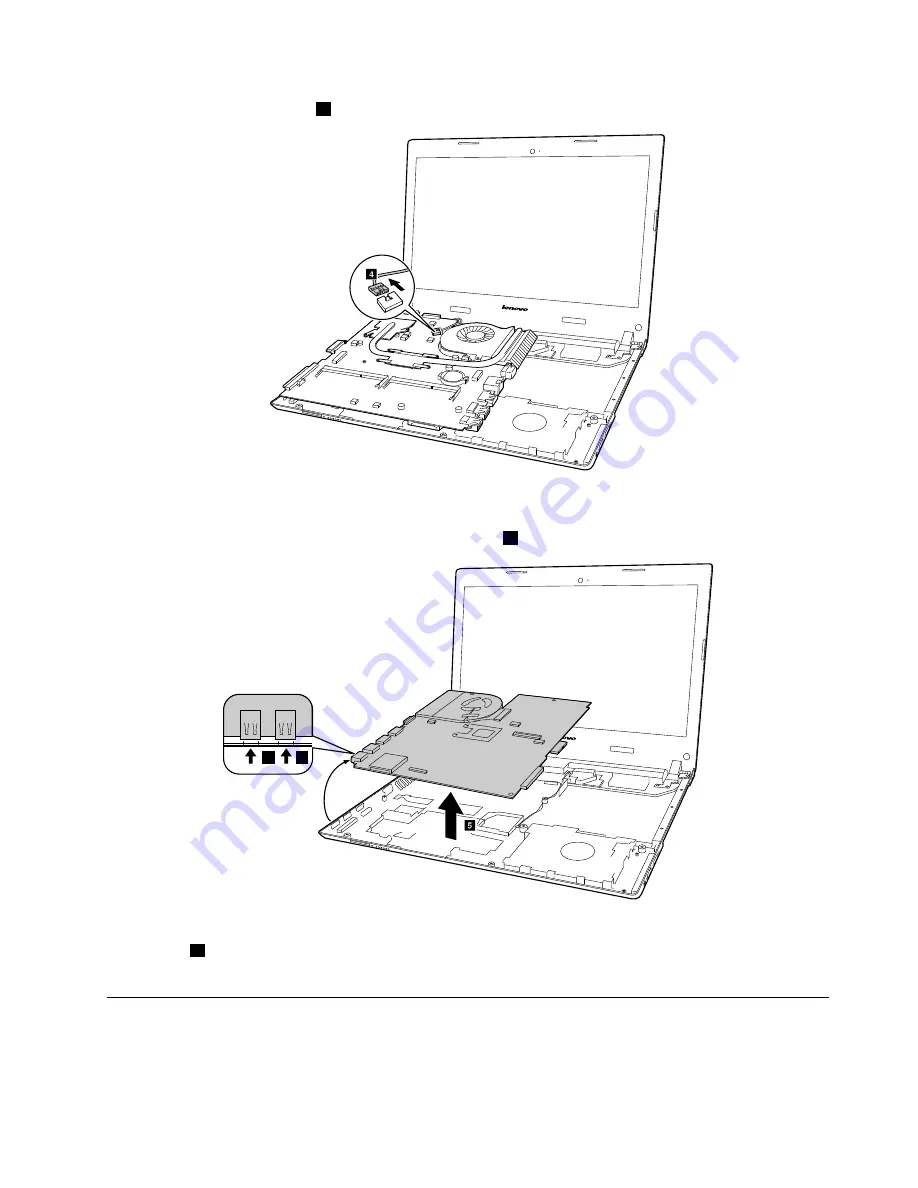
Unplug DC-in cable connector

4

.

d

When installing:

Ensure that the connectors are attached firmly.

Remove the system board in the direction shown by arrow

5

.

e

a

a

When installing:

When attaching the system board to the base cover, adjust the placement of the USB ports

as shown in

a

, and make sure that they are attached to the holes on the base cover as shown. Improper

placement of those jacks might cause a damage.

1110 Battery Board, Thermal fan assembly and Heat Sink assembly

For access, remove these FRUs in order:

“1010 External battery pack” on page 52

“1020 Keyboard” on page 52

Chapter 10

.

Removing or replacing a FRU

69

Summary of Contents for E50-80

Page 1: ...Hardware Maintenance Manual Lenovo E50 80 ...

Page 2: ...nder Appendix A Notices on page 81 First Edition January 2015 Copyright Lenovo 2015 LIMITED AND RESTRICTED RIGHTS NOTICE If data or software is delivered pursuant a General Services Administration GSA contract use reproduction or disclosure is subject to restrictions set forth in Contract No GS 35F 05925 ...

Page 3: ...password 27 Chapter 6 Status indicators 29 Chapter 7 Function keys 31 Chapter 8 Locations 33 Locating FRUs and CRUs 33 Major FRUs and CRUs 34 LCD FRUs 40 Miscellaneous parts and other FRUs 41 Chapter 9 FRU replacement notices 49 Screw notices 49 Chapter 10 Removing or replacing a FRU 51 General guidelines 51 1010 External battery pack 52 1020 Keyboard 52 1030 Optical disk drive 54 1040 Base cover ...

Page 4: ...ii Hardware Maintenance Manual ...

Page 5: ...bleshoot problems Important This manual is intended only for trained service technicians who are familiar with Lenovo products Use this manual along with the advanced diagnostic tests to troubleshoot problems effectively Before servicing a Lenovo product be sure to read all the information under Chapter 1 Safety information on page 1 and Chapter 2 Important service information on page 19 Copyright...

Page 6: ...iv Hardware Maintenance Manual ...

Page 7: ...tool case away from walk areas so that other people will not trip over it Do not wear loose clothing that can be trapped in the moving parts of a machine Make sure that your sleeves are fastened or rolled up above your elbows If your hair is long fasten it Insert the ends of your necktie or scarf inside clothing or fasten it with a non conductive clip about 8 centimeters 3 inches from the end Do n...

Page 8: ...he safety sections of maintenance information Use extreme care when measuring high voltages Regularly inspect and maintain your electrical hand tools for safe operational condition Do not use worn or broken tools and testers Never assume that power has been disconnected from a circuit First check that it has been powered off Always look carefully for possible hazards in your work area Examples of ...

Page 9: ...d or tampered with Handling devices that are sensitive to electrostatic discharge Any computer part containing transistors or integrated circuits ICs should be considered sensitive to electrostatic discharge ESD ESD damage can occur when there is a difference in charge between objects Protect against ESD damage by equalizing the charge so that the machine the part the work mat and the person handl...

Page 10: ...ct system function Proper grounding of the electrical outlet can be verified by a certified electrician Safety notices multilingual translations The safety notices in this section are provided in the following languages English Arabic Brazilian Portuguese French German Hebrew Japanese Korean Spanish Traditional Chinese DANGER DANGER DANGER 4 Hardware Maintenance Manual ...

Page 11: ...DANGER DANGER DANGER DANGER DANGER Chapter 1 Safety information 5 ...

Page 12: ...6 Hardware Maintenance Manual ...

Page 13: ...PERIGO PERIGO PERIGO PERIGO Chapter 1 Safety information 7 ...

Page 14: ...PERIGO PERIGO PERIGO PERIGO DANGER 8 Hardware Maintenance Manual ...

Page 15: ...DANGER DANGER DANGER DANGER DANGER DANGER Chapter 1 Safety information 9 ...

Page 16: ...DANGER VORSICHT VORSICHT VORSICHT VORSICHT 10 Hardware Maintenance Manual ...

Page 17: ...VORSICHT VORSICHT VORSICHT VORSICHT Chapter 1 Safety information 11 ...

Page 18: ...12 Hardware Maintenance Manual ...

Page 19: ...Chapter 1 Safety information 13 ...

Page 20: ...14 Hardware Maintenance Manual ...

Page 21: ...Chapter 1 Safety information 15 ...

Page 22: ...16 Hardware Maintenance Manual ...

Page 23: ...Chapter 1 Safety information 17 ...

Page 24: ...18 Hardware Maintenance Manual ...

Page 25: ...I BIOS downloads are installed before replacing any FRUs listed in this manual After a system board is replaced ensure that the latest UEFI BIOS is loaded to the system board before completing the service action To download software fixes drivers and UEFI BIOS go to http support lenovo com en_US downloads detail page LegacyDocID DRVR MATRIX and follow the instructions on the screen Use the followi...

Page 26: ...ajor FRUs FRU part numbers and FRU descriptions for a product at an MT serial number level Examples of major FRUs are hard disk drive system board liquid crystal display LCD and memory module To identify the major FRUs for a product do the following 1 Go to http www lenovo com support 2 Click Warranty Services 3 Click Check Warranty Status 4 On the Warranty Status Lookup page click Parts Lookup 5 ...

Page 27: ...og and run the test again If the error does not recur do not replace the FRU Be careful not to replace a nondefective FRU What to do first When you return a FRU you must include the following information in the parts exchange form or parts return form that you attach to it 1 Name and phone number of service technician 2 Date of service 3 Date on which the machine failed 4 Date of purchase 5 Failur...

Page 28: ... adapter is functional 4 Insert a straightened paper clip into the novo button to reset the computer If the computer is still powered on it means that the ac power adapter is functional 5 Turn off the computer 6 Disconnect the ac power adapter and turn on the computer If the computer can be turned on it means that the battery pack is functional If you suspect a power problem see the appropriate on...

Page 29: ...otification area displays the percentage of the battery power remained To check for detailed battery status information do the following For Windows 7 Open the Power Manager program and click the Battery tab For Windows 8 and Windows 8 1 Open the Lenovo Settings program and click Power Note If the external battery pack becomes hot it may not be able to charge Remove it from the computer and leave ...

Page 30: ...24 Hardware Maintenance Manual ...

Page 31: ... system will enter the user interface for system recovery automatically Please follow the prompt to insert the backup discs to complete the whole recovery process Note The recovery process might take up to 2 hours Power management To reduce power consumption the computer has three power management modes screen blank sleep and hibernation Screen blank mode for the Windows 7 operating system only If...

Page 32: ...hile it is docked to the docking station or the port replicator do not undock it before resuming normal operation If you do undock it and then try to resume normal operation you will get an error message and you will have to restart the system If you have defined one of the following actions as the event that causes the system to go into hibernation mode perform that action Closing the lid Pressin...

Page 33: ... disk passwords the system administrator enters both in the same operation The system administrator then provides the user hard disk password to the system user Attention If the user hard disk password has been forgotten check whether a master hard disk password has been set If it has it can be used for access to the hard disk drive If no master hard disk password is available neither Lenovo nor L...

Page 34: ...28 Hardware Maintenance Manual ...

Page 35: ...or Solid green The battery charge level is between 80 and 100 or the battery discharge level is between 20 and 100 Slow blinking green The battery charge level is between 20 and 80 and charging is continuing Slow blinking amber The battery charge level is between 5 and 20 and charging is continuing Solid amber The battery has between 5 and 20 charge Fast blinking amber The battery charge or discha...

Page 36: ...30 Hardware Maintenance Manual ...

Page 37: ...mera Fn F5 For Windows 7 Change wireless settings For Windows 8 1 Enable Disables airplane mode Fn F6 Mute Unmutes sound Fn F7 Enables Disables microphone Fn F8 Enables Disables touch pad Fn F9 For Windows 7 Opens Control Panel For Windows 8 1 Opens the Settings charm F10 For Windows 7 Opens Windows Search For Windows 8 1 Opens the Search charm F11 Views the programs that you have opened F12 For W...

Page 38: ...32 Hardware Maintenance Manual ...

Page 39: ...st of CRUs for your product in this Hardware Maintenance Manual An electronic version of this manual can be found at http www lenovo com UserManuals Follow the on screen instructions to find the manual for your product You might be required to return the defective part that is replaced by the CRU When return is required 1 return instructions a prepaid shipping label and a container will be include...

Page 40: ... LCD unit LCD unit No No 2 Keyboard Keyboard bezel assembly No Yes 3 Memory Module Memory Module M471B5674QH0 YK0 Yes No 11202451 3 Memory Module Memory Module HMT425S6AFR6A PB 2GB DDR3L 1600 Yes No 11201299 3 Memory Module Memory Module RMT3170MK58F8F 1600 2GB DDR3L 1600 Yes No 11202301 3 Memory Module Memory Module RMT3190ME76F8F 1600 2GB Yes No 5M30G04992 34 Hardware Maintenance Manual ...

Page 41: ...d C E50 70 No No 5C50H44839 5 Upper case Upper CoverCE50 70W TP TPCB FP No No 5CB0H44855 5 Upper case Upper CoverCE50 70W TP TPCB NFP No No 5CB0H44847 6 System board MB C E50 80 NOK 2G 5500 G DOC No No 5B20H56221 6 System board MB C E50 80 W8P 2G 5500 G DOC No No 5B20H56218 6 System board MB C E50 80 W8S 2G 5500 G DOC No No 5B20H56206 6 System board MB C E50 80 NOK 2G 5500 G NDOC No No 5B20H56198 ...

Page 42: ...E50 80 W8S 1G 5200 G NDOC No No 5B20H56228 6 System board MB C E50 80 NOK UMA 5200 G DOC No No 5B20H56219 6 System board MB C E50 80 W8P UMA 5200 G DOC No No 5B20H56207 6 System board MB C E50 80 W8S UMA 5200 G DOC No No 5B20H56205 6 System board MB C E50 80 NOK UMA 5200 G NDOC No No 5B20H56199 6 System board MB C E50 80 W8P UMA 5200 G NDOC No No 5B20H56190 6 System board MB C E50 80 W8S UMA 5200 ...

Page 43: ...MB C E50 80 W8S 1G 5005 G DOC No No 5B20H56264 6 System board MB C E50 80 NOK 1G 5005 G NDOC No No 5B20H56256 6 System board MB C E50 80 W8P 1G 5005 G NDOC No No 5B20H56258 6 System board MB C E50 80 W8S 1G 5005 G NDOC No No 5B20H56249 6 System board MB C E50 80 NOK UMA 5005 G DOC No No 5B20H56240 6 System board MB C E50 80 W8P UMA 5005 G DOC No No 5B20H56242 6 System board MB C E50 80 W8S UMA 500...

Page 44: ...4A01 14 4V32Wh Yes No 121500243 7 Battery Battery 4 cell 2 2Ah LG L13L4A01 14 4V32Wh Yes No 121500244 8 Wlan Intel WP1 3160 1x1ac BT M 2 ROW Combo BT ROM update Yes No SW10A11511 8 Wlan Intel StP 7265 2x2ac BT M 2 Combo Non Vpro Sku Yes No SW10A11518 8 Wlan Cbt BCM43162 1x1AC BT4 0 PCIE M 2 WLAN V2 Yes No SW10A11586 8 Wlan Ltn NFA345 1x1AC BT4 0 PCIE M 2 WLAN V2 Yes No SW10A11628 8 Wlan Cbt BCM431...

Page 45: ...400rpm ST1000LM024 6G 9 5mm 5 4K 1T HDD Yes No 16200385 15 HDD Hard Disk Drive 1TB 5400rpm WD10JPCX 24UE4T0 6G 9 5mm 5 4K 1T HDD Yes No 16200393 15 HDD Hard Disk Drive 1TB 5400rpm TSB MQ01ABD100 6G 9 5mm 5 4K 1T HDD Yes No 16200429 15 SSHD Solid State Hybrid Drive Seagate KahunaR ST500LM000 7mm 5 4K 500G 8G Yes No 5H20H24608 15 SSHD Solid State Hybrid Drive 500G 8 G Hybrid ST500LM000 6G 7mm 500G 8...

Page 46: ...50 70 No No 5C50H44762 21 Battery Board Battery Board C E50 70 No No 5C50H44813 22 Docking board DockingBoardCE50 70W BK LED Mat No No 5C50H44785 LCD FRUs 1 2 2 6 3 4 4 5 8 7 8 2 Table 4 LCD FRUs No FRU parts FRU descriptions Self service CRU Optional service CRU PN number 1 LCD bezel LCD BezelCE50 70W CAM MAG Mylar No No 5B30H44763 1 LCD bezel LCDBezelCE50 70NCAM W MAG Mylar No No 5B30H44768 2 Sc...

Page 47: ...iscellaneous parts and other FRUs Table 5 Miscellaneous part FRU descriptions Self service CRU Optional service CRU PN number a HDD Bracket C E50 70 No No 5B40H44869 b ODD bracket ODD C E50 70 No No 5B40H44790 c Touch Pad board TP Board C E40 30 No No 5C10G07301 d Audio board cable IO Board C E50 70 No No 5C10H44874 e DC in cable DC IN Board C E40 30 UMA only for E40 No No 5C10G07314 e DC in cable...

Page 48: ...es No 145000585 Power code Europe 3pin Longwell LP 34A H03VV F LS 18 1m code Yes No 145000553 Power code Europe 3pin VOLEX M2511 HO3VV F VAC5S 1m code Yes No 145000525 Power code Europe 3pin lux 0033 H03VV F 0 75 3C 0011 1m code Yes No 145500001 Power code US 3pin LINETEK LP 30B SPT 2 LS15 1m code Yes No 145000594 Power code US 3pin Longwell LP 30B SPT 2 18AWG LS 18 1m code Yes No 145000562 Power ...

Page 49: ...5000531 Power code Taiwan 3pin lux 0019 VCTF 0 75 3C 0021 1m code Yes No 145500007 Power code Korea 3pin LINETEK LS15 H05VV F LP E04A 1m code Yes No 145000590 Power code Korea 3pin Longwell LP 486 KTLH03VV F LS 5 1m code Yes No 145000558 Power code Korea 3pin VOLEX M2511 KETI IEC VAC5S 1m code Yes No 145000533 Power code Korea 3pin lux 0033 H03VV F 0 75 3C 0011 1m code Yes No 145500008 Power code ...

Page 50: ...3pin LINETEK LS15 H03VV F LP 38 1m code Yes No 145000598 Power code Denmark 3pin Longwell LP 40 H03VV F LS 18 1m code Yes No 145000566 Power code Denmark 3pin VOLEX MP233D H03VV F VAC5S 1m code Yes No 145000534 Power code Denmark 3pin lux 0048 H03VV F 0 75 3C 0011 1m code Yes No 145500014 Power code Argentina 3pin LINETEK LS15 H03VV F LP39 1m code Yes No 145000599 Power code Argentina 3pin Longwel...

Page 51: ... No Yes 25214808 Keyboard Sunrex Slovenian103KeyT6G1DFBlkKBlkFrameKBD No Yes 25214809 Keyboard Sunrex Swiss103KeyT6G1DFBlkKBlkFrameKBD No Yes 25214810 Keyboard Sunrex USInter102KeyT6G1DFBlkKBlkFrameKBD No Yes 25214811 Keyboard Sunrex Czh Slk103KeyT6G1DFBlkKBlkFrameKBD No Yes 25214812 Keyboard Sunrex Bulgarian103KeyT6G1DFBlkKBlkFrameKBD No Yes 25214813 Keyboard Sunrex India102KeyT6G1DFBlkKBlkFrameK...

Page 52: ...CCYBlkKBlkFrameKBD No Yes 25214727 Keyboard Spanish103KeyT6G1CCYBlkKBlkFrameKBD No Yes 25214728 Keyboard Turkish103KeyT6G1CCYBlkKBlkFrameKBD No Yes 25214729 Keyboard Thailand102KeyT6G1CCYBlkKBlkFrameKBD No Yes 25214730 Keyboard Portugue103KeyT6G1CCYBlkKBlkFrameKBD No Yes 25214731 Keyboard LatinSpa103KeyT6G1CCYBlkKBlkFrameKBD No Yes 25214732 Keyboard CanadFrEn103KeyT6G1CCYBlkKBlkFrameKBD No Yes 252...

Page 53: ... No Yes 25214749 Keyboard Swiss103KeyT6G1CCYBlkKBlkFrameKBD No Yes 25214750 Keyboard USInter102KeyT6G1CCYBlkKBlkFrameKBD No Yes 25214751 Keyboard Czh Slk103KeyT6G1CCYBlkKBlkFrameKBD No Yes 25214752 Keyboard Bulgarian103KeyT6G1CCYBlkKBlkFrameKBD No Yes 25214753 Keyboard India102KeyT6G1CCYBlkKBlkFrameKBD No Yes 25214754 Chapter 8 Locations 47 ...

Page 54: ...48 Hardware Maintenance Manual ...

Page 55: ...ions to find the manual for your product You might be required to return the defective part that is replaced by the CRU When return is required 1 return instructions a prepaid shipping label and a container will be included with the replacement CRU and 2 you might be charged for the replacement CRU if Lenovo does not receive the defective CRU within thirty 30 days of your receipt of the replacemen...

Page 56: ...correct screw If you have a torque screwdriver tighten all screws firmly to the torque specified in the screw information table for each step Ensure that torque screwdrivers are calibrated correctly following country specifications 50 Hardware Maintenance Manual ...

Page 57: ...cumentation for full details Note The illustrations used in this section are of the Lenovo E40 unless otherwise stated General guidelines When removing or replacing a FRU be sure to observe the following general guidelines 1 Do not try to service any computer unless you have been trained and certified An untrained person runs the risk of damaging parts 2 Before replacing any FRU review Chapter 9 F...

Page 58: ...battery pack FRU should not be replaced unless this diagnostic test shows that the battery is defective The only exception to this is if the battery pack is physically damaged or a customer is reporting a possible safety issue If the Lenovo Solution Center program is not installed on the computer the customer should download and install the program to diagnose the battery pack before getting a non...

Page 59: ...teps of the keyboard Remove two screws 1 E40 a a Remove three screws 1 E50 a a a Step Screw quantity Color Torque 1 M2 0 6mm flat head nylok coated Black 1 85 0 15kgf cm Chapter 10 Removing or replacing a FRU 53 ...

Page 60: ...on shown by arrow 3 b c c Lift the keyboard a little 4 and then detach the connector in the direction shown by arrows 5 6 f e d When installing Make sure that the connector is firmly attached 1030 Optical disk drive For access remove these FRUs in order 1010 External battery pack on page 52 54 Hardware Maintenance Manual ...

Page 61: ...ew quantity Color Torque 1 SCREW M2 6mm flat head nylok coated Black 1 85 0 15kgf cm Insert a screwdriver into the screw hold and push the optical driver in the direction shown by arrow 2 Pull the optical drive out in the direction shown by arrow 3 b c Chapter 10 Removing or replacing a FRU 55 ...

Page 62: ...5 0 15kgf cm 1040 Base cover assembly For access remove these FRUs 1010 External battery pack on page 52 Removal steps of the base cover assembly Remove the screws 1 that secure the base cover assembly Remove the base cover assembly 2 b a a b Step Screw quantity Color Torque 1 SCREW M2 5 6mm flat head nylok coated 2 Black 3 0 0 3kgf cm 56 Hardware Maintenance Manual ...

Page 63: ...urn the replaced part to the customer or provide a letter to the customer stating the original label part number serial number and product key The following illustration shows the location of each label on E40 a b f c e d a Rating label d Wlan label b Rating print label e BT label c COA label windows 7 GML label for windows 8 1 f Indonesia rating label The following illustration shows the location...

Page 64: ...t loss of data Before removing the drive have the user make a backup copy of all the information on it if possible Never remove the drive while the system is operating or in suspend mode Removal steps of the hard disk drive or the solid state drive Remove the screws 1 a a Step Screw quantity Color Torque M2 5 6mm flat head nylon coated 2 E40 Black 3 0 0 3kgf cm 1 M2 5 4mm flat head nylon coated 2 ...

Page 65: ...3mm flat head nylon coated 4 Black 3 0 0 3kgf cm When installing Ensure that the hard disk drive or solid state hybrid drive is firmly attached 1060 Wireless LAN Bluetooth card For access remove these FRUs in order 1010 External battery pack on page 52 1040 Base cover assembly on page 56 Chapter 10 Removing or replacing a FRU 59 ...

Page 66: ...hat has two antenna connectors plug the black cable 1st MAIN into the jack labeled MAIN or 1 on the card and the white cable 2nd AUX into jack labeled AUX or 2 on the card 2 In models with a wireless LAN card that has three antenna connectors plug the black cable 1st MAIN into the jack labeled MAIN or 1 the grey cable 3rd into jack labeled 1 and the white cable 2nd AUX into jack labeled 2 on the c...

Page 67: ...e memory module in firmly and pivot it downward until it snaps into place Ensure that the memory module is firmly installed in the slot and does not move easily 1080 Upper case For access remove these FRUs in order 1010 External battery pack on page 52 1020 Keyboard on page 52 1030 Optical disk drive on page 54 1040 Base cover assembly on page 56 1050 Hard disk drive or solid state hybrid drive on...

Page 68: ...nine screws 1 and three screws 2 on the bottom E50 a a a a a a a a b b b a Step Screw quantity Color Torque M2 5 6mm flat headed nylon coated 8 E40 Black 3 0 0 3kgf cm 1 M2 5 7mm flat headed nylon coated 9 E50 Black 3 0 0 3kgf cm 2 M2 0 2mm flat headed nylon coated Black 1 85 0 15kgf cm 62 Hardware Maintenance Manual ...

Page 69: ...ed firmly Remove the upper case in the direction shown by arrow 5 e 1090 Audio board audio board cable power board touch pad board cable finger printer board LED board and ODD switch board For access remove these FRUs in order 1010 External battery pack on page 52 1020 Keyboard on page 52 1030 Optical disk drive on page 54 1040 Base cover assembly on page 56 Chapter 10 Removing or replacing a FRU ...

Page 70: ...ad board cable finger printer board LED board and ODD switch board Detach Audio board cable connector 1 Remove one screw 2 and then remove the audio board in the direction shown by arrow 3 b c a a Step Screw quantity Color Torque 2 M2 5 4 mm flat head nylon coated 1 silver 3 0 0 3kgf cm When installing make sure that the audio board cable connector is firmly attached 64 Hardware Maintenance Manual...

Page 71: ...gf cm Detach the connector 6 and then remove the touch pad board cable in the direction shown by arrow 7 g f When installing make sure that the touch pad board cable connector is firmly attached Remove one screw 8 and then remove the finger printer bracket in the direction shown by arrow 9 b a Step Screw quantity Color Torque 8 M2 3mm flat head nylon coated 1 black 1 85 0 15kgf cm Chapter 10 Remov...

Page 72: ... remove the ODD switch board in the direction shown by arrow 16 E50 o o p n Step Screw quantity Color Torque 4 M2 5 4mm flat head nylon coated 2 silver 3 0 0 3kgf cm 1100 System board Important notices for handling the system board When handling the system board read the following Be careful not to drop the system board on a bench top that has a hard surface such as metal wood or composite 66 Hard...

Page 73: ...l battery pack on page 52 1020 Keyboard on page 52 1030 Optical disk drive on page 54 1040 Base cover assembly on page 56 1050 Hard disk drive or solid state hybrid drive on page 58 1060 Wireless LAN Bluetooth card on page 59 1080 Upper case on page 61 1090 Audio board audio board cable power board touch pad board cable finger printer board LED board and ODD switch board on page 63 Removal steps o...

Page 74: ...rew quantity Color Torque M2 5mm flat headed nylon coated 1 E40 Silver 1 85 0 15kgf cm 2 M2 6mm flat headed nylon coated 1 E50 Black 1 85 0 15kgf cm M2 5 6mm flat headed nylon coated 3 E40 Black 3 0 0 3kgf cm 3 M2 5 4mm flat headed nylon coated 4 E50 Silver 3 0 0 3kgf cm 68 Hardware Maintenance Manual ...

Page 75: ... to the base cover adjust the placement of the USB ports as shown in a and make sure that they are attached to the holes on the base cover as shown Improper placement of those jacks might cause a damage 1110 Battery Board Thermal fan assembly and Heat Sink assembly For access remove these FRUs in order 1010 External battery pack on page 52 1020 Keyboard on page 52 Chapter 10 Removing or replacing ...

Page 76: ...d Loosen two screws 1 and then remove the battery board in the direction shown by arrow 2 E50 a a b Step Screw quantity Color Torque 1 M2 0 3mm flat headed nylon coated 2 Black 1 85 0 15kgf cm Removal steps of the thermal fan assembly Loosen six screws 3 and one screw 4 d c c c c c c Step Screw quantity Color Torque 3 M2 0 3mm flat headed nylon coated 6 Black 1 85 0 15kgf cm M2 0 5mm flat headed n...

Page 77: ...onnector in the direction shown by arrow 6 f When installing Ensure that the fan connector is attached firmly Remove the thermal fan assembly in the direction shown by arrow 7 g Chapter 10 Removing or replacing a FRU 71 ...

Page 78: ... System board on page 66 Removal steps of the speaker assembly docking LED lens and docking bracket Release antenna and LVDS cables from the cable guide loosen four screws 1 and remove the speakers 2 a a a a b b Step Screw quantity Color Torque M2 3mm big head nylon coated 4 E40 Black 1 85 0 15kgf cm 1 M2 3mm big head nylon coated 4 E50 Black 1 85 0 15kgf cm Attention As you route the cables ensur...

Page 79: ...52 1020 Keyboard on page 52 1030 Optical disk drive on page 54 1040 Base cover assembly on page 56 1050 Hard disk drive or solid state hybrid drive on page 58 1060 Wireless LAN Bluetooth card on page 59 1080 Upper case on page 61 1090 Audio board audio board cable power board touch pad board cable finger printer board LED board and ODD switch board on page 63 1100 System board on page 66 1120 Spea...

Page 80: ...t headed nylon coated 2 E40 Silver 3 0 0 3kgf cm 3 M2 5 5mm flat headed nylon coated 2 E50 Black 3 0 0 3kgf cm When installing Route the antenna cables along the cable guides As you route the cables make sure that they are not subjected to any tension Tension could cause the cables to be damaged by the cable guides or a wire to be broken Make sure that the LCD connector is attached firmly and make...

Page 81: ...ble 5 E40 e Loose one screw 5 and then remove the docking board docking cable and DC in cable in the direction shown by arrow 6 E50 e f Step Screw quantity Color Torque 5 M2 5 4mm flat head nylon coated 1 Silver 3 0 0 3kgf cm Chapter 10 Removing or replacing a FRU 75 ...

Page 82: ...LED lens and docking bracket on page 72 1130 LCD unit docking board docking cable and DC in cable on page 73 Removal steps of the LCD front bezel Remove the covers 1 and then remove two screws 2 b b a a Step Screw quantity Color Torque 2 M2 5 4mm flat headed nylon coated 2 Silver 3 0 0 3kgf cm Remove the LCD front bezel in the direction shown by arrow 3 c c c c 1150 LCD panel EDP cable and hinges ...

Page 83: ... the LCD panel EDP cable and hinges Remove four screws 1 and then remove the LCD panel 2 a a a a b b b Step Screw quantity Color Torque M2 5 4mm flat headed nylon coated 4 E40 Black 3 0 0 3kgf cm 1 M2 3mm flat headed nylon coated 4 E50 Black 1 85 0 15kgf cm Disconnect the EDP cable connector 3 a When installing Ensure that the connector is attached firmly Remove two screws 4 and the remove the hin...

Page 84: ...ase cover assembly on page 56 1050 Hard disk drive or solid state hybrid drive on page 58 1060 Wireless LAN Bluetooth card on page 59 1080 Upper case on page 61 1090 Audio board audio board cable power board touch pad board cable finger printer board LED board and ODD switch board on page 63 1100 System board on page 66 1120 Speaker assembly docking LED lens and docking bracket on page 72 1130 LCD...

Page 85: ...cal disk drive on page 54 1040 Base cover assembly on page 56 1050 Hard disk drive or solid state hybrid drive on page 58 1060 Wireless LAN Bluetooth card on page 59 1080 Upper case on page 61 1090 Audio board audio board cable power board touch pad board cable finger printer board LED board and ODD switch board on page 63 1100 System board on page 66 1120 Speaker assembly docking LED lens and doc...

Page 86: ...le guides and secure the antenna boards with adhesive tapes As you route the cables make sure that they are not subjected to any tension Tension could cause the cables to be damaged by the cable guides or a wire to be broken 80 Hardware Maintenance Manual ...

Page 87: ...e publication Lenovo may make improvements and or changes in the product s and or the program s described in this publication at any time without notice The products described in this document are not intended for use in implantation or other life support applications where malfunction may result in injury or death to persons The information contained in this document does not affect or change Len...

Page 88: ...rks The following terms are trademarks of Lenovo in the United States other countries or both Lenovo OneKey Microsoft Windows and Windows Server are trademarks of the Microsoft group of companies DisplayPort Mini DisplayPort mDP and VESA are trademarks of the Video Electronics Standards Association Other company product or service names may be the trademarks or service marks of others 82 Hardware ...

Page 89: ...PROM Electrically Erasable Programmable Read Only Memory EFI Extensible Firmware Interface EPO emergency power off ESD electrostatic discharge EU European Union FCC Federal Communications Commission FRU Field Replaceable Unit GAV General Announce Variant GPU graphics processing unit HDD hard disk drive HDMI high definition multimedia interface ICs integrated circuits ICCID integrate circuit card i...

Page 90: ...dvanced Technology Attachment SIM subscriber identity module SVP supervisor password TFTs thin film transistors UEFI Unified Extensible Firmware Interface USB Universal Serial Bus UUID universally unique identifier VGA video graphics array VRAM video random access memory WAN wide area network 84 Hardware Maintenance Manual ...

Page 91: ......

Page 92: ......

Reviews: