
Connectors and LEDs
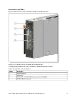
Figure 5 shows the front panel of the Cisco Catalyst Switch Module 3012.
Figure 5. Front panel of the Cisco Catalyst Switch Module 3012
The components visible on the front of the switch module are identified in Table 7.
Table 7. Components on the front panel
Callout
Description
1
USB console port
2
Mode button
3
Switch LEDs - Fault LED (left) and system power LED (right)
4
10/100/1000 Ethernet ports
Network cabling requirements
Cisco Catalyst Switch Module 3012 for BladeCenter (withdrawn product)
12


