Step 3.
Disconnect all cables attached to the computer. This includes power cords, input/output (I/O)
cables, and any other cables that are connected to the computer. Refer to “Left and right views”
and “Rear view” for help with locating the various connectors.
Step 4.
Remove the stand base. Refer to “Removing the stand base”.
Step 5.
Remove the foot cover. Refer to “Removing the foot cover”.
Step 6.
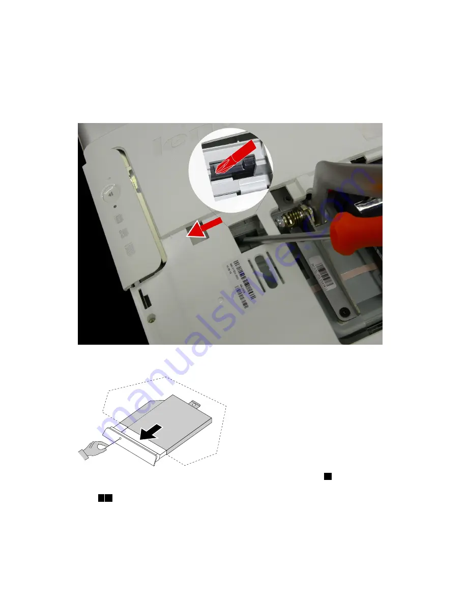
Locate the optical removal notch, and then use a screw driver push the optical drive out.
Step 7.
Push a small iron stick (paper clip) into the small hole on the optical drive cover so that the disk
springs out as shown.
Step 8.
Remove the 2 screws that secure the optical drive to the metal bracket.
1
Step 9.
Use a small flat head screwdriver to press and push out the pins that secure the cover to the
disk.
2 3
28
Lenovo C50 Series All-In-One Computer Hardware Maintenance Manual
Summary of Contents for C50 Series
Page 1: ...Lenovo C50 Series All In One Computer Hardware Maintenance Manual Machine Types F0B1 C50 30 ...
Page 2: ......
Page 3: ...Lenovo C50 Series All In One Computer Hardware Maintenance Manual Machine Types F0B1 C50 30 ...
Page 6: ...iv Lenovo C50 Series All In One Computer Hardware Maintenance Manual ...
Page 8: ...2 Lenovo C50 Series All In One Computer Hardware Maintenance Manual ...
Page 16: ...10 Lenovo C50 Series All In One Computer Hardware Maintenance Manual ...
Page 18: ...12 Lenovo C50 Series All In One Computer Hardware Maintenance Manual ...
Page 24: ...18 Lenovo C50 Series All In One Computer Hardware Maintenance Manual ...
Page 64: ...58 Lenovo C50 Series All In One Computer Hardware Maintenance Manual ...


