background image

Generelle Informationen:

Das Gerät erfüllt die Schutzanforderungen nach EN 55024 und EN 55022 Klasse A.

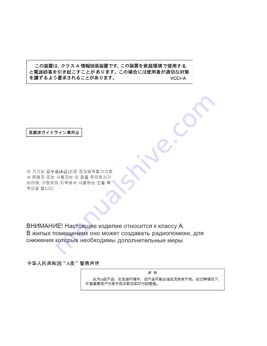
Japan VCCI Class A statement

This is a Class A product based on the standard of the Voluntary Control Council for Interference (VCCI). If
this equipment is used in a domestic environment, radio interference may occur, in which case the user may
be required to take corrective actions.

Japan Electronics and Information Technology Industries Association
(JEITA) statement

Japan Electronics and Information Technology Industries Association (JEITA) Confirmed Harmonics
Guidelines with Modifications (products greater than 20 A per phase)

Korea Communications Commission (KCC) statement

This is electromagnetic wave compatibility equipment for business (Type A). Sellers and users need to pay
attention to it. This is for any areas other than home.

Russia Electromagnetic Interference (EMI) Class A statement

People's Republic of China Class A electronic emission statement

78

BladeCenter HS22 Blade ServerInstallation and User's Guide

Summary of Contents for BladeCenter HS22

Page 1: ...BladeCenter HS22 Blade Server Installation and User s Guide Machine Types 7870 1936 1911 ...

Page 2: ...n documents on the IBM Documentation CD The most recent version of this document is available at http www ibm com systems support Thirteenth Edition August 2012 Copyright Lenovo 2012 2015 LIMITED AND RESTRICTED RIGHTS NOTICE If data or software is delivered pursuant a General Services Administration GSA contract use reproduction or disclosure is subject to restrictions set forth in Contract No GS ...

Page 3: ...xpansion card 38 Removing a horizontal compact form factor expansion card 39 Installing a CIOv form factor expansion card 40 Removing a CIOv form factor expansion card 41 Installing a storage interface card 42 Removing a storage interface card 45 Completing the installation 47 Closing the blade server cover 48 Installing the blade server in a BladeCenter unit 48 Updating the blade server configura...

Page 4: ...Federal Communications Commission FCC statement 76 Industry Canada Class A emission compliance statement 76 Avis de conformité à la réglementation d Industrie Canada 76 Australia and New Zealand Class A statement 76 European Union EMC Directive conformance statement 76 Germany Class A statement 77 Japan VCCI Class A statement 78 Japan Electronics and Information Technology Industries Association J...

Page 5: ...alleert eerst de veiligheidsvoorschriften Ennen kuin asennat tämän tuotteen lue turvaohjeet kohdasta Safety Information Avant d installer ce produit lisez les consignes de sécurité Vor der Installation dieses Produkts die Sicherheitshinweise lesen Prima di installare questo prodotto leggere le Informazioni sulla Sicurezza Les sikkerhetsinformasjonen Safety Information før du installerer dette prod...

Page 6: ...caution statement are in the Safety Information document under Statement 1 Be sure to read all caution and danger statements in this documentation before you perform the procedures Read any additional safety information that comes with your system or optional device before you install the device Statement 1 DANGER Electrical current from power telephone and communication cables is hazardous To avo...

Page 7: ...the lithium battery use only IBM Part Number 33F8354 or an equivalent type battery recommended by the manufacturer If your system has a module containing a lithium battery replace it only with the same module type made by the same manufacturer The battery contains lithium and can explode if not properly used handled or disposed of Do not Throw or immerse into water Heat to more than 100 C 212 F Re...

Page 8: ... avoid direct exposure to the beam Class 1 Laser Product Laser Klasse 1 Laser Klass 1 Luokan 1 Laserlaite Appareil A Laser de Classe 1 Statement 4 18 kg 39 7 lb 32 kg 70 5 lb 55 kg 121 2 lb CAUTION Use safe practices when lifting Statement 8 CAUTION Never remove the cover on a power supply or any part that has the following label attached vi BladeCenter HS22 Blade ServerInstallation and User s Gui...

Page 9: ...er certain conditions To avoid these hazards ensure that your system electrical requirements do not exceed branch circuit protection requirements Refer to the information that is provided with your device for electrical specifications Statement 21 CAUTION Hazardous energy is present when the blade is connected to the power source Always replace the blade cover before installing the blade Statement...

Page 10: ...at all power cords are disconnected from the power source Rack Safety Information Statement 2 DANGER Always lower the leveling pads on the rack cabinet Always install stabilizer brackets on the rack cabinet Always install servers and optional devices starting from the bottom of the rack cabinet Always install the heaviest devices in the bottom of the rack cabinet UL regulatory information This dev...

Page 11: ...tp www ibm com systems support 2 Under Product support click BladeCenter 3 Under Popular links click Software and device drivers 4 Click BladeCenter HS22 to display the matrix of downloadable files for the blade server The blade server comes with a limited warranty For information about the terms of the warranty and getting service and assistance see the Warranty and Support Information document f...

Page 12: ...the side of the control panel on the front of the blade server and on a label on the side of the blade server that is visible when the blade server is not in the BladeCenter unit Note The illustrations in this document might differ slightly from the hardware Important Do not place the label on the blade server itself or in any way block the ventilation holes on the blade server 0000 0000 0000 0000...

Page 13: ...e This document is in PDF on the IBMDocumentation CD It contains translated environmental notices Integrated Management Module User s Guide This document is in PDF on the IBM Web site at http www ibm com systems support This document explains how to use the functions of the IMM installed in an IBM server The IMM works with IBM System x Server Firmware to provide systems management capability for S...

Page 14: ...y If Autostart is disabled or is not enabled for all users use one of the following procedures If you are using a Windows operating system insert the CD into the CD or DVD drive and click Start Run In the Open field type e win32 bat where e is the drive letter of the CD or DVD drive and click OK If you are using Red Hat Linux insert the CD into the CD or DVD drive then run the following command fr...

Page 15: ...ures and the dimensions of the blade server Notes 1 Power cooling removable media drives external ports and advanced system management are provided by the BladeCenter unit 2 The operating system in the blade server must provide USB support for the blade server to recognize and use USB media drives and devices The BladeCenter unit uses USB for internal communications with these devices The followin...

Page 16: ...6000 ft Blade server on 5 C to 30 C 41 F to 86 F Altitude 1800 m to 4000 m 6000 ft to 13000 ft Blade server off 5 C to 55 C 23 F to 131 F Altitude 60 m to 1800 m 197 ft to 6000 ft Blade server off 5 C to 45 C 23 F to 113 F Altitude 1800 m to 4000 m 6000 ft to 13000 ft Blade server storage 40 C to 60 C 40 F to 140 F Humidity 8 to 85 Particulate contamination Attention Airborne particulates and reac...

Page 17: ... core IntelXeon processor 5500 series microprocessors For more information about supported microprocessors and their part numbers see the Problem Determination and Service Guide Integrated network support All of the blade server models come with an integrated Broadcom dual port Gigabit Ethernet controller The controller supports connections to a 10 Mbps 100 Mbps or 1000 Mbps network through an Eth...

Page 18: ...lity and serviceability RAS These RAS features help to ensure the integrity of the data that is stored in the blade server the availability of the blade server when you need it and the ease with which you can diagnose and correct problems The blade server has the following RAS features Customer upgrade of Flash ROM resident code and diagnostics Power Policy 24 hour support center VPD on Memory Pro...

Page 19: ... director resources It is updated every 6 to 8 weeks Support for IBM and non IBM servers desktop computers workstations and notebook computers Support for systems management industry standards Integration into leading workgroup and enterprise systems management environments Ease of use training and setup IBM Director also provides an extensible platform that supports advanced server tools that are...

Page 20: ...00000 00000 00000 000 000 000 00000 00000 00000 00000 10 BladeCenter HS22 Blade ServerInstallation and User s Guide ...

Page 21: ...the blade server is not communicating with the Advanced Management Module Flashing slowly The blade server has power supplied and is ready to be turned on Lit continuously The blade server has power and is turned on Activity LED When this green LED is lit it indicates that there is activity on the external storage device or network Location LED The system administrator can remotely turn on this bl...

Page 22: ... two digit number of the blade server bay in which the blade server is installed A blade server that occupies more than one blade server bay is identified by the lowest bay number that it occupies If there is no response when you press the KVM select button you can use the Advanced Management Module Web interface to determine whether local control has been disabled on the blade server See on page ...

Page 23: ...essor in the blade server is initializing and synchronizing with the management module the power on LED flashes rapidly and the power control button on the blade server does not respond This process can take approximately two minutes after the blade server has been installed 2 While the blade server is starting the power on LED on the front of the blade server is lit and does not flash See Blade s...

Page 24: ...ly shutdown of the operating system if this feature is supported by the operating system If the operating system stops functioning you can press and hold the power control button for more than 4 seconds to turn off the blade server The management module can turn off the blade server through the Advanced Management Module Web interface For additional information see the IBMBladeCenter Management Mo...

Page 25: ...cted If an error occurs in the expansion blade the fault LED on the blade device on which the expansion blade is installed is also lit Additional information about the error is provided by the light path LEDs in the expansion blade see the Problem Determination and Service Guide that comes with your server for more information Chapter 2 Power controls and indicators 15 ...

Page 26: ...16 BladeCenter HS22 Blade ServerInstallation and User s Guide ...

Page 27: ...updates for your blade server complete the following steps 1 Go to http www ibm com systems support 2 Under Product support click BladeCenter 3 Under Popular links click Software and device drivers 4 Click BladeCenter HS22 to display the matrix of downloadable files for the blade server To download the latest updates for Websphere DataPower SOA Appliance complete the following steps 1 Go to http w...

Page 28: ...dule or filler Each hot swap SAS bay contains a SAS storage drive or filler Make sure that the ventilation holes on the blade server are not blocked The blade server battery must be operational If the battery becomes defective replace it immediately For instructions see the Problem Determination and Service Guide Handling static sensitive devices Use this information to observe the static sensitiv...

Page 29: ... unit without a blade server expansion unit or filler module installed in each blade server bay When you remove the blade server note the blade server bay number Reinstalling a blade server into a different blade server bay from the one it was removed from can have unintended consequences Some configuration information and update options are established according to blade server bay number if you ...

Page 30: ...ore you begin read Safety on page iii and Installation guidelines on page 17 Step 2 If the blade server is installed in a BladeCenter unit remove it see Removing the blade server from the BladeCenter unit on page 19 for instructions Step 3 Carefully lay the blade server on a flat static protective surface with the cover side up Step 4 Press the blade server cover release on each side of the blade ...

Page 31: ...adjacent blade bays in the BladeCenter unit Enough power modules must be installed in the BladeCenter unit to power the blade bays in which you install the blade server and expansion units 4 The following illustration shows an optional expansion unit in a blade server 5 The illustrations in this document might differ slightly from your hardware To install an optional expansion unit complete the fo...

Page 32: ...ion unit Step 9 If additional expansion units are being installed repeat steps 4 through 8 for each expansion blade otherwise continue with step 11 Step 10 Follow the instructions provided with the expansion unit to install an option in the expansion unit Step 11 If you have other devices to install or remove do so now otherwise go to Completing the installation on page 47 Removing an optional exp...

Page 33: ...IBM WebSphere DataPower Integration Blade XI50B Type 4195 appliance The blade server has two SAS storage bays for installing hot swap storage drives such as a hot swap SAS hard disk drive One storage drive might already be installed in the blade server in storage bay 0 If the blade server is equipped with one storage drive you can install an additional drive in storage bay 1 The blade server suppo...

Page 34: ...lade server has two SAS hot swap storage bays for installing or removing hot swap storage devices such as a SAS storage drive To remove a hot swap hard disk drive or drive filler complete the following steps 00000 00000 00000 000 000 000 00000 00000 00000 00000 Step 1 Before you begin read Safety on page iii and Installation guidelines on page 17 Step 2 Press the release latch orange on the storag...

Page 35: ...erver can support a minimum of 1 GB and a maximum of 48 GB of system memory on the system board in a blade server with one processor If two microprocessors are installed the blade server can support a minimum of 2 GB and a maximum of 96 GB of system memory There are two different memory modes Independent channel mode Independent channel mode gives a maximum of 96 GB of usable memory with one CPU i...

Page 36: ...he order that memory DIMMs are installed to use a mirrored channel mode Table 5 System memory configuration for mirrored channel mode 1 microprocessor DIMM socket Installed memory 1 2 3 4 5 6 7 8 9 10 11 12 2 DIMMs X X 4 DIMMs X X X X Table 6 System memory configuration for mirrored channel mode 2 microprocessors DIMM socket Installed memory 1 2 3 4 5 6 7 8 9 10 11 12 4 DIMMs X X X X 6 DIMMs X X X...

Page 37: ... installing DIMMs on the system board remove the expansion unit see Removing an optional expansion unit on page 22 Step 7 Locate the DIMM connectors see Blade server connectors on page 14 Determine which DIMM connector you will be installing memory into Step 8 If a DIMM filler or another memory module is already installed in the DIMM connector remove it see Removing a memory module on page 28 Note...

Page 38: ...e retaining clips the DIMM has not been correctly installed Press the DIMM firmly into the connector and then press the retaining clips toward the DIMM until the tabs are fully seated When the DIMM is correctly installed the retaining clips are parallel to the sides of the DIMM Step 12 If the DIMM access door is open use your fingers to close it Step 13 If you have other devices to install or remo...

Page 39: ...o remove from the blade server Attention To avoid breaking the retaining clips or damaging the DIMM connectors handle the clips gently Step 6 Move the retaining clips on the ends of the DIMM connector to the open position by pressing the retaining clips away from the center of the DIMM connector Note To access DIMM connector seven through twelve use your fingers to lift the DIMM access door 000000...

Page 40: ...tructions 4 Remove the blade server cover see Removing the blade server cover on page 20 for instructions 5 If an expansion unit is installed over the expansion unit you want to install the adapter in remove that expansion unit see Removing an optional expansion unit on page 22 for instructions 6 If you have not already done so touch the static protective package that contains the GPU adapter to a...

Page 41: ...er cable A as shown in the following illustration A B 14 Connect the cable to the expansion unit system board Replace the retention bracket and tighten the screws B as shown in the illustration above If you have other devices to install or remove do so now otherwise go to Completing the installation on page 47 Removing a GPU adapter from the BladeCenter GPU expansion unit Use this information to r...

Page 42: ...ns Step 3 Remove the blade server cover see Removing the blade server cover on page 20 for instructions Step 4 If an expansion blade is installed on the expansion blade containing the adapter you want to remove remove it see Removing an optional expansion unit on page 22 Step 5 Remove the expansion blade riser assembly from the BladeCenter GPU expansion blade a Disconnect the auxiliary power cable...

Page 43: ...er assembly out of the expansion unit system board Step 6 Carefully turn over the expansion unit riser assembly and use a Phillips screwdriver to remove the four non captive retaining screws as shown in the following illustration Store the screws in a safe location Chapter 3 Installing options 33 ...

Page 44: ...for shipping that are supplied to you Installing a microprocessor and heat sink Use this information to install a microprocessor and heat sink in the blade server The following illustration shows how to install a microprocessor and heat sink in the blade server Microprocessor 1 and heat sink Microprocessor 2 Heat sink Microprocessor heat sink filler To install a microprocessor and heat sink comple...

Page 45: ...lly open position approximately a 135 angle as shown c If a dust cover is installed over the microprocessor socket lift the dust cover from the socket d Touch the static protective package that contains the microprocessor to any unpainted metal surface on the BladeCenter unit or any unpainted metal surface on any other grounded rack component then remove the microprocessor from the package e Remov...

Page 46: ...t to the microprocessor you installed a If you installed microprocessor 1 install the memory module into DIMM connector 1 see Installing a memory module on page 24 b If you installed microprocessor 2 install the memory module into DIMM connector 6 see Installing a memory module on page 24 Step 5 If you are using a single microprocessor make sure that memory modules are installed in DIMM socket 2 a...

Page 47: ...ue with step Step 2 on page 35 Installing a USB Flash key Use these instructions to install a USB Flash key in the blade server Note For instruction on installing the USB Flash key in the IBM WebSphere DataPower Integration Blade XI50B Type 4195 appliance see the WebSphere DataPower Integration Blade XI50B pdsg Addendum document available on the IBM Web site at http www ibm com systems support The...

Page 48: ...llation of the SAS connectivity card in the system board installing the card in an expansion unit is similar The blade server has two I O expansion connectors on the system board One connector supports horizontal combination form factor CFFh expansion cards and the other connector supports vertical combination I O CIOv expansion cards See http www ibm com servers eserver serverproven compat us for...

Page 49: ...on the blade expansion connector remove it by using your fingers to lift the cover from the blade expansion connector Step 7 Touch the static protective package that contains the expansion card to any unpainted metal surface on the BladeCenter unit or any unpainted metal surface on any other grounded rack component then remove the expansion card from the package Step 8 Orient the expansion card an...

Page 50: ...ion card standoff Installing a CIOv form factor expansion card Use these instructions to install a CIOv form factor expansion card in the blade server Note This section does not apply to the IBM WebSphere DataPower Integration Blade XI50B Type 4195 appliance The blade server supports a vertical combination I O CIOv expansion card and a horizontal combination form factor CFFh expansion card The fol...

Page 51: ...he CIOv expansion connector see Blade server connectors on page 14 Step 7 Orient the connector on the expansion card with the CIOv expansion connector on the system board then press the card into the CIOv expansion connector Step 8 Firmly press on the indicated locations to seat the expansion card Note For device driver and configuration information to complete the installation of the expansion ca...

Page 52: ...component then remove the expansion card from the package Step 6 Locate the CIOv expansion connector see Blade server connectors on page 14 Step 7 Using your fingers move the retaining clips away from the CIOv card then lift the card out of the connector Installing a storage interface card Use this information to install a storage interface card in the blade server Note This section does not apply...

Page 53: ...ep 2 If the blade server is installed in a BladeCenter unit remove it see Removing the blade server from the BladeCenter unit on page 19 for instructions Step 3 Remove the blade server cover see Removing the blade server cover on page 20 for instructions Step 4 If an optional expansion unit is installed remove the expansion unit see Removing an optional expansion unit on page 22 Step 5 Locate the ...

Page 54: ...e end of the cable marked EXPANSION CARD then with the blue side of the cable end facing up carefully insert the cable end into the cable connector on the ServeRAID controller Step 9 Orient the connector on the storage interface card with the CIOv expansion connector on the system board then press the storage interface card into the CIOv expansion connector Step 10 Firmly press on the indicated lo...

Page 55: ...l or remove do so now otherwise go to Completing the installation on page 47 Removing a storage interface card Use this information to remove a storage interface card from the blade server Note This information does not apply to the IBM WebSphere DataPower Integration Blade XI50B Type 4195 appliance The storage interface card controls the SAS hot swap storage drives The following illustrations and...

Page 56: ...an be removed separately from each other Step 5 To remove the storage interface card complete the following steps a Locate the storage interface card installed in the CIOv connector on the system board see Blade server connectors on page 14 b Gently push the retaining clips away from the expansion card then lift the card out of the expansion card connector c Remove the cable from the storage inter...

Page 57: ...ional expansion unit on page 21 for information on installing the expansion unit Step 2 Close the blade server cover unless you installed an optional expansion unit that has its own cover see Closing the blade server cover on page 48 Statement 21 CAUTION Hazardous energy is present when the blade server is connected to the power source Always replace the blade server cover before installing the bl...

Page 58: ...0000000 0000000 000000 000000 000000 000000 000000 00000000 00000000 00000000 00000000 00000000 00000000 Step 3 If you removed an expansion unit from the blade server install it now see Installing an optional expansion unit on page 21 Step 4 Lower the cover so that the slots at the rear slide down onto the pins at the rear of the blade server as shown in the illustration Before you close the cover...

Page 59: ...must be installed in all four power module bays For additional information see the Installation and User s Guide that comes with the BladeCenter unit 2 If you are reinstalling a blade server that you removed you must install it in the same blade bay from which you removed it Some blade server configuration information and update options are established according to blade server bay number Reinstal...

Page 60: ...e BladeCenter T unit BladeCenter T unit only For detailed instructions for reinstalling the bezel assembly see the Installation and User s Guide that comes with the BladeCenter T unit If this is the initial installation of the blade server in the BladeCenter unit you must configure the blade server through the Setup utility and install the blade server operating system See Updating the blade serve...

Page 61: ...he BladeCenter unit See the documentation that comes with the BladeCenter unit for information about the input output connectors The blade server has two selection buttons on the control panel the media tray select button and the keyboard video mouse select button See Blade server controls and LEDs on page 11 for information about these buttons and their functions The Ethernet controllers on the b...

Page 62: ...52 BladeCenter HS22 Blade ServerInstallation and User s Guide ...

Page 63: ...at reduces hands on time and user errors Wizards and other default settings enable customization capabilities The low touch set once and walk away feature reduces the hands on server setup time from days to minutes particularly for larger deployments For information about this tool see http www 947 ibm com support entry portal docdisplay lndocid TOOL FASTSET IBM ServerGuide Setup and Installation ...

Page 64: ...he server When you make changes through other choices in the Setup utility some of those changes are reflected in the system information you cannot change settings directly in the system information This choice is on the full Setup utility menu only System Summary Select this choice to view configuration information including the ID speed and cache size of the microprocessors machine type and mode...

Page 65: ...rting the system whenever a nonmaskable interrupt NMI occurs Disabled is the default Network Configuration Select this choice to view the system management network interface port the IMM MAC address the current IMM IP address and host name define the static IMM IP address subnet mask and gateway address specify whether to use the static IP address or have DHCP assign the IMM IP address save the ne...

Page 66: ...diagnostic programs to get more information about error codes that occur See the Problem Determination and Service Guide for instructions on running the diagnostic programs Important If the system error LED on the front of the server is lit but there are no other error indications clear the IMM system event log Also after you complete a repair or correct an error clear the IMM system event log to ...

Page 67: ...lled and uses that information during setup to configure the hardware The ServerGuide program simplifies operating system installations by providing updated device drivers and in some cases installing them automatically You can download a free image of the ServerGuide Setup and Installation CD or purchase the CD from the ServerGuide fulfillment Web site at http www ibm com systems management serve...

Page 68: ...ion The ServerGuide program can reduce the time it takes to install an operating system It provides the device drivers that are required for the hardware and for the operating system that you are installing This section describes a typical ServerGuide operating system installation Note Features and functions can vary slightly with different versions of the ServerGuide program 1 After you have comp...

Page 69: ...lade server can manage To start the PXE boot agent utility program complete the following steps 1 Turn on the server see Turning on the blade server on page 13 2 When the Broadcom NetXtreme Boot Agent vX X X prompt is displayed press Ctrl S You have 2 seconds by default to press Ctrl S after the prompt is displayed 3 Follow the instructions on the screen to change the settings of the selected item...

Page 70: ...ach Ethernet port to an I O module bay is assigned by the operating system You do not have to set any jumpers or configure the controller for the blade server operating system However you must install a device driver to enable the blade server operating system to address the Ethernet controller For device drivers and information about configuring the Ethernet controller complete the following step...

Page 71: ... the keyboard video and mouse Step 2 When the Press Ctrl C to start LSI Logic Configuration Utility prompt is displayed press Ctrl C Step 3 Use the arrow keys to select the controller from the list of adapters then press Enter Step 4 Follow the instructions on the screen to change the settings of the selected items then press Enter If you select SAS Topology or Advanced Adapter Properties addition...

Page 72: ...he watchdog timeouts to prevent the server from restarting unexpectedly Use the following steps to disable the LAN over USB interface from the IMM Web interface a Log in to the IMM on which you want to disable the USB device driver interface b In the navigation pane click System Settings and scroll down to the Miscellaneous area c Select the Do not allow commands on USB interface check box to disa...

Page 73: ...DSA update packages Perform the following steps to install ibm_rndis_server_os inf Note These steps only need to be performed if the server is running a Windows operating system and the ibm_rndis_server_os inf file has not been previously installed The file needs to be installed only once It is required by Windows operating systems to detect and use the LAN over USB functionality 1 Obtain a Window...

Page 74: ...e use a static IP address of 169 254 95 130 with a subnet mask of 255 255 0 0 Note Older Linux distributions might not detect the LAN over USB interface and might require manual configuration For information about configuring LAN over USB on specific Linux distributions see the IBM white paper Transitioning to UEFI and IMM on the IBM web site see Related documentation on page 3 for information on ...

Page 75: ... complete the following steps Step 1 While the blade server is on press the KVM select button on the front of the blade server to associate the BladeCenter unit CD drive with the blade server Step 2 Insert the CD and restart the blade server If the CD does not start see ServerGuide problems on page 68 Step 3 Follow the instructions on the screen to complete the following tasks a Select your langua...

Page 76: ...ibed in this document 1 Go to http www ibm com systems support 2 Under Select product or service type for support click BladeCenter 3 Under Popular Links click Operating system installation 4 Under Choose the system you want instructions for click BladeCenter HS22 5 Under the Installation select the operating system you want to install 66 BladeCenter HS22 Blade ServerInstallation and User s Guide ...

Page 77: ...icate the detection of a problem See the Problem Determination and Service Guide for more information Troubleshooting tables These tables list problem symptoms and actions to correct the problems See the Problem Determination and Service Guide for your blade server Light path diagnostics Use light path diagnostics LEDs on the system board to diagnose system errors If the system error LED on the sy...

Page 78: ...e sure that the CD drive is associated with the blade server that you are configuring Make sure that the blade server supports the ServerGuide program and has a bootable CD or DVD drive If the startup boot sequence settings have been changed make sure that the CD drive is first in the startup sequence The RAID configuration program cannot view all installed drives or the operating system cannot be...

Page 79: ...rs serverproven compat us to make sure that the hardware and software is supported by your IBM product Go to http www ibm com supportportal to check for information to help you solve the problem Gather the following information to provide to IBM Support This data will help IBM Support quickly provide a solution to your problem and ensure that you receive the level of service for which you might ha...

Page 80: ...stems intellistation How to send DSA data to IBM Use the IBM Enhanced Customer Data Repository to send diagnostic data to IBM Before you send diagnostic data to IBM read the terms of use at http www ibm com de support ecurep terms html You can use any of the following methods to send diagnostic data to IBM Standard upload http www ibm com de support ecurep send_http html Standard upload with the s...

Page 81: ... SERV 1 800 426 7378 In the U S and Canada hardware service and support is available 24 hours a day 7 days a week In the U K these services are available Monday through Friday from 9 a m to 6 p m The following lists related documentation for servicing IBM WebSphere DataPower Integration Blade XI50B appliance IBM WebSphere DataPower Integration Blade XI50B Type 4195 Installation and User s Guide ht...

Page 82: ...72 BladeCenter HS22 Blade ServerInstallation and User s Guide ...

Page 83: ...er of express or implied warranties in certain transactions therefore this statement may not apply to you This information could include technical inaccuracies or typographical errors Changes are periodically made to the information herein these changes will be incorporated in new editions of the publication IBM may make improvements and or changes in the product s and or the program s described i...

Page 84: ...orted drives that are available from IBM Maximum memory might require replacement of the standard memory with an optional memory module Each solid state memory cell has an intrinsic finite number of write cycles that the cell can incur Therefore a solid state device has a maximum number of write cycles that it can be subjected to expressed as total bytes written TBW A device that has exceeded this...

Page 85: ... HEPA filters that meet MIL STD 282 The deliquescent relative humidity of the particulate contamination must be more than 60 2 The room must be free of conductive contamination such as zinc whiskers Gaseous Copper Class G1 as per ANSI ISA 71 04 19853 Silver Corrosion rate of less than 300 Å in 30 days 1 ASHRAE 52 2 2008 Method of Testing General Ventilation Air Cleaning Devices for Removal Efficie...

Page 86: ...tors or by unauthorized changes or modifications to this equipment Unauthorized changes or modifications could void the user s authority to operate the equipment This device complies with Part 15 of the FCC Rules Operation is subject to the following two conditions 1 this device may not cause harmful interference and 2 this device must accept any interference received including interference that m...

Page 87: ...asse A Geräte müssen mit folgendem Warnhinweis versehen werden Warnung Dieses ist eine Einrichtung der Klasse A Diese Einrichtung kann im Wohnbereich Funk Störungen verursachen in diesem Fall kann vom Betreiber verlangt werden angemessene Maßnahmen zu ergreifen und dafür aufzukommen Deutschland Einhaltung des Gesetzes über die elektromagnetische Verträglichkeit von Geräten Dieses Produkt entsprich...

Page 88: ...ormation Technology Industries Association JEITA statement Japan Electronics and Information Technology Industries Association JEITA Confirmed Harmonics Guidelines with Modifications products greater than 20 A per phase Korea Communications Commission KCC statement This is electromagnetic wave compatibility equipment for business Type A Sellers and users need to pay attention to it This is for any...

Page 89: ...Taiwan Class A compliance statement Appendix B Notices 79 ...

Page 90: ...80 BladeCenter HS22 Blade ServerInstallation and User s Guide ...

Page 91: ...n Setup Utility 53 PXE Boot Agent Utility program 53 Setup utility 53 updating 50 with ServerGuide 58 configuring Gigabit Ethernet controller 60 RAID array 60 UEFI compatible devices 60 configuring a RAID array 60 configuring your blade server 53 connectors 14 I O expansion card 14 input output 51 memory 14 microprocessor 14 SAS hard disk drives 14 system board 14 contamination particulate and gas...

Page 92: ...nectivity card installing 38 IBM Director 6 9 IBM Taiwan product service 71 IMM LAN over USB 61 IMM controller settings 54 important notices 74 InfiniBand high speed card I O expansion card installing 38 information center 70 installation completing 47 procedure 30 installation instructions 66 installation order for memory modules 24 installing blade server 49 CFFh 38 CIOv form factor expansion ca...

Page 93: ... 24 P particulate contamination 75 password power on 57 PCI bus control settings 54 People s Republic of China Class A electronic emission statement 78 port input output 51 power throttling 6 power on password 57 Preboot eXecution Environment PXE option 54 disabling 54 enabling 54 problems hardware 67 problems solving 67 processor summary information 54 product data 54 product service IBM Taiwan 7...

Page 94: ...port 6 storage interface card 45 installing 42 removing 45 SAS controller 45 support web page custom 70 system information 54 system MAC addresses 54 system reliability 18 system security 54 system summary information 54 system board components location of 9 system board connectors 14 systems management 9 T Taiwan Class A electronic emission statement 79 telecommunication regulatory statement 76 t...

Page 95: ......

Page 96: ...Part Number 00D9283 Printed in China 1P P N 00D9283 1P00D9283 ...

Reviews: