background image

10

Hardware Replacement guide

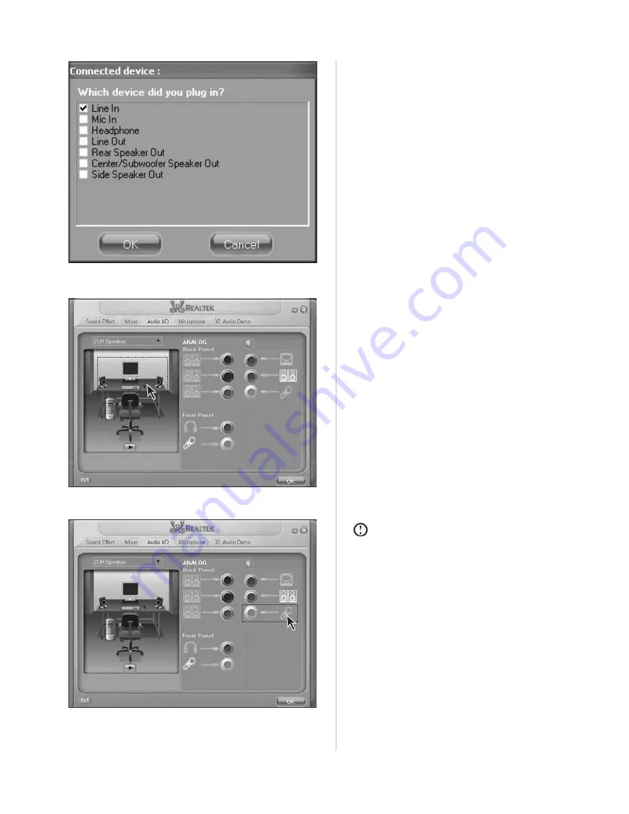
Note: 

The situation must be avoided

w h e n   c o n n e c t i n g   d e v i c e s   –
microphone must be connected to the
connector as illustrated.

You can test whether the connection and

setting is correct by clicking the

corresponding speaker icon in the picture

on the left.

If you want to connect other audio devices,

connect the audio cables respectively to the

I/O connectors on the rear panel. Every time

a connector is connected, a dialog box

pops up as illustrated. Select appropriate

name according to the device connected

with the audio cable.

Summary of Contents for 8822

Page 1: ...WORLDWIDE PARTNER Hardware Replacement Guide Type 8822 8823 ...

Page 2: ... on the front of the computer 2 8822 2 8823 3 Locating connectors on the rear of the computer 5 8822 5 8823 6 Chapter 2 Replacing hardware 13 Replacing the keyboard 13 Replacing the mouse 13 Replacing the internal speaker 14 Completing the parts replacement 14 ...

Page 3: ......

Page 4: ... do not open the static protective package containing the new part until the defective part has been removed from the computer and you are ready to install the new part When you handle parts and other computer components take these precautions to avoid static electricity damage Limit your movement Movement can cause static electricity to build up around you Always handle parts and other computer c...

Page 5: ...puter This section shows the various external connectors on the computer to which you can attach external devices 8822 F 1 F 2 1 1 1 2 1 3 F 1 The top button 1 1 Reset Key Press this key to restart computer forcibly It is recommended to take this operation with caution 1 2 Hard Disk Drive Indicator Indicates read write operations of the hard disk 1 3 Power Switches Press this key to turn on off co...

Page 6: ...peaker Headphone Connector Used to connect speakers or headphones If it is necessary to connect the headphone remove the speaker plug and insert the headphone plug D 3 Microphone Connector Used to connect the microphone and input the sound received by the microphone into the computer 8823 F 1 F 2 F 3 F 4 F 5 F 6 F 7 F 1 Low noise Mode Press this key to reduce the noise of computers after entering ...

Page 7: ... connectors such as USB will be shown as below MS Pro Duo CF MD SM MMC SD D 5 D 1 D 2 D 3 D 4 D 6 D 1 USB Connector Used to connect USB devices D 2 Speaker Headphone Connector Used to connect speakers or headphones If it is necessary to connect the headphone remove the speaker plug and insert the headphone plug D 3 Microphone Connector Used to connect the microphone and input the sound received by...

Page 8: ...nnect PS 2 keyboard Serial port Used to connect devices with serial port COM port Parallel port Used to connect devices with parallel port Onboard graphics card connector Used to output monitor signals VGA signals through the signal cable connected with the monitor On models with external graphics card onboard graphics card signals are shielded with no VGA signal outputs some models are equipped w...

Page 9: ...some models are equipped with external graphics card Used to attach your computer to a telephone line for modem use some models equipped with this connector Used to attach a telephone line to your computer for modem use some models equipped with this connector Audio in connector Used to receive audio signals Audio out connector Used to attach a speaker or headphones Microphone connector Used to at...

Page 10: ...r Used to connect USB devices Ethernet connector Used to connect LAN or broadband devices External graphics card connector Used to output monitor signals VGA signals through the signal cable connected with the monitor If the graphics card is equipped with S Video connector and cabled to a TV pictures displayed on the monitor screen may be redirected to the TV some models are equipped with external...

Page 11: ...und Effect Mixer and 3D Audio Demo You can open Audio I O and configure the input and output settings for the audio card Step 2 Select Sound Manager in the audio settings menu as illustrated Set as below Step 1 Right click the audio settings icon located in the lower right corner of your desktop ...

Page 12: ...lation of the audio I O connectors on the rear panel Step 1 Select 2CH Speaker on the screen as illustrated Then connect the Line in cable of the speaker to the green connector Set for speaker pre configured as 2 0 Step 2 Check Line Out in the dialog box popped up as illustrated ...

Page 13: ... connection and setting is correct by clicking the corresponding speaker icon in the picture on the left If you want to connect other audio devices connect the audio cables respectively to the I O connectors on the rear panel Every time a connector is connected a dialog box pops up as illustrated Select appropriate name according to the device connected with the audio cable ...

Page 14: ...ven t connected it to the Mic In connector and check Mic In as illustrated in the pop up window You will get the error instruction as illustrated This instruction box will not display if microphone is connected to the front Mic In connector ...

Page 15: ...of the speaker Y 1 Y 2 Y 6 Y 5 Y 3 Y 4 Y 1 Volume adjusting knob Y 2 Bass effect adjusting knob Y 3 Connect to mainframe Speaker headphone connector Y 4 Speaker power switch Y 5 Speaker power cord Y 6 Primary secondary speaker connection cable ...

Page 16: ...tor 2 1 at the rear of the computer or to a USB connector 2 2 at either the front or rear of the computer Locate the connector for the keyboard 2 1 2 2 4 Disconnect the failing keyboard cable from the computer and connect the new keyboard cable to the same connector 5 Go to Completing the parts replacement Replacing the mouse 1 Remove any media diskettes CDs or tapes from the drives shut down the ...

Page 17: ...able to the same connector 5 Go to Completing the parts replacement Completing the parts replacement After replacing a failed part you need to install any other removed parts install the computer cover and reconnect any cables including telephone lines and power cords To complete the installation 1 Ensure that all components have been reassembled correctly and that no tools or loose screws are lef...

Page 18: ...www lenovo com Version 1 0 31027072 ...

Reviews: