To replace the system board, do the following:
1. Remove all media from the drives and turn off all attached devices and the server. Then, disconnect all
power cords from electrical outlets and disconnect all cables that are connected to the server.
2. Remove the server cover. See “Removing the server cover” on page 37.
3. Lay the server on its side for easier access to the system board.
4. Remove all memory modules and PCI cards that are currently installed. See “Installing or removing a
memory module” on page 41 and “Installing or replacing a PCI card” on page 56.
5. Remove the heat sink and fan assembly from the failing system board. See “Replacing the heat sink and
fan assembly” on page 69.
Note:
Place the heat sink and fan assembly on its side so that the thermal grease on the bottom of it
does not get in contact with anything.
6. Remove the microprocessor from the failing system board. See “Replacing the microprocessor” on
page 75.
7. Remove the battery from the failing system board. See “Replacing the system board battery” on page 78.
8. Note the location of all cable connections on the system board and disconnect all cables. See “Locating
parts on the system board” on page 15.
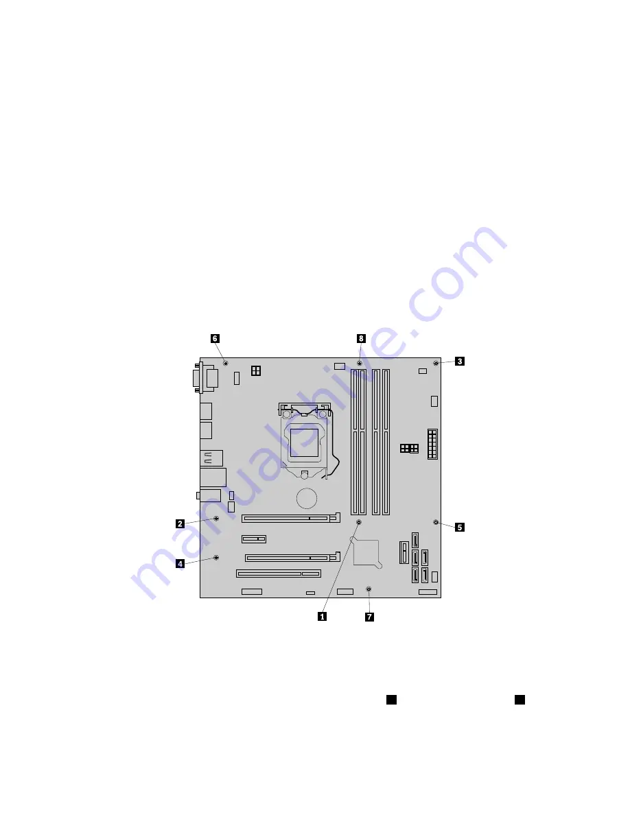
9. Remove the eight screws that secure the system board to the chassis by following the sequence shown
in the following illustration.
10. Carefully lift the failing system board out of the chassis.
11. Remove the retention module from the bottom of the failing system board and then install it to the
new system board.
12. Position the new system board into the chassis so that the screw holes in the new system board are
aligned with those in the chassis. Install the eight screws that secure the system board to the chassis in
the reverse order that they were removed; that is, install the screw
8
first and install the screw
1
last.
13. Remove the microprocessor socket cover from the new system board.
14. Install the memory modules, PCI cards, battery, microprocessor, and heat sink and fan assembly that
you removed from the failing system board to the new system board.
80
ThinkServer TS140 Hardware Maintenance Manual
Summary of Contents for 70A0
Page 1: ...ThinkServer TS140 Hardware Maintenance Manual Machine Types 70A0 70A1 70A4 and 70A5 ...
Page 16: ...4 ThinkServer TS140 Hardware Maintenance Manual ...
Page 18: ...6 ThinkServer TS140 Hardware Maintenance Manual ...
Page 30: ...18 ThinkServer TS140 Hardware Maintenance Manual ...
Page 32: ...20 ThinkServer TS140 Hardware Maintenance Manual ...
Page 106: ...94 ThinkServer TS140 Hardware Maintenance Manual ...
Page 120: ...108 ThinkServer TS140 Hardware Maintenance Manual ...
Page 121: ......
Page 122: ......


