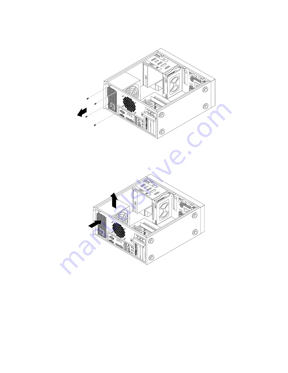
4. Remove the four screws at the rear of the chassis that secure the power supply assembly.
Figure 51. Removing the screws that secure the power supply assembly
5. Slide the power supply assembly a little bit forward and then remove it from the chassis.
Figure 52. Removing the power supply assembly
6. Ensure that the new power supply assembly is the correct replacement.
7. Install the new power supply assembly into the chassis so that the screw holes in the power supply
assembly align with those in the chassis.
8. Install and tighten the four screws to secure the power supply assembly.
Note:
Use only screws provided by Lenovo.
9. Reconnect the power supply assembly cables to the system board and each of the drives.
10. Secure the power supply assembly cables with the cable clips and ties in the chassis.
68
ThinkServer TS140 Hardware Maintenance Manual
Summary of Contents for 70A0
Page 1: ...ThinkServer TS140 Hardware Maintenance Manual Machine Types 70A0 70A1 70A4 and 70A5 ...
Page 16: ...4 ThinkServer TS140 Hardware Maintenance Manual ...
Page 18: ...6 ThinkServer TS140 Hardware Maintenance Manual ...
Page 30: ...18 ThinkServer TS140 Hardware Maintenance Manual ...
Page 32: ...20 ThinkServer TS140 Hardware Maintenance Manual ...
Page 106: ...94 ThinkServer TS140 Hardware Maintenance Manual ...
Page 120: ...108 ThinkServer TS140 Hardware Maintenance Manual ...
Page 121: ......
Page 122: ......


