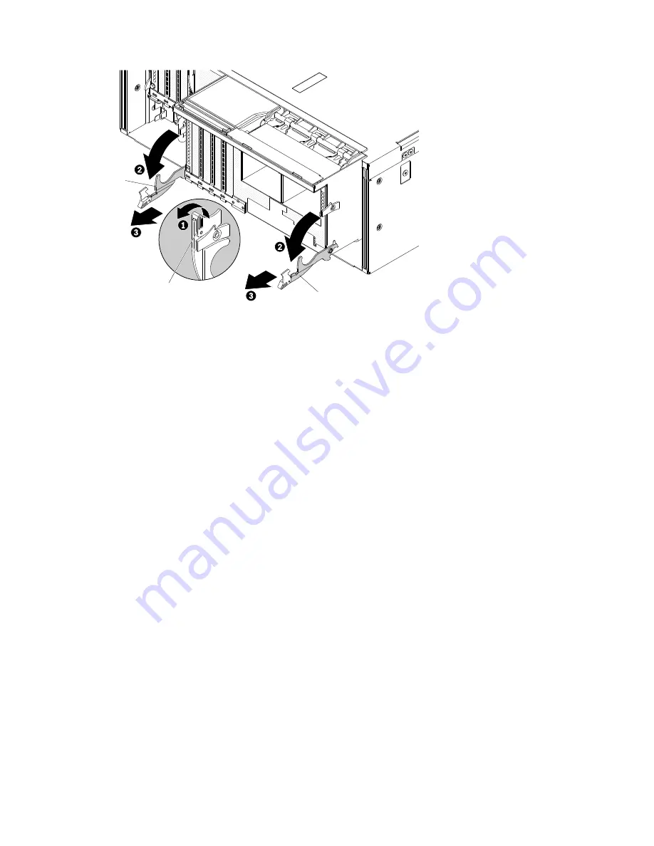
Release latch
Handle
Handle
5. Slide the standard I/O book out of the shuttle and set it aside.
6. Open the adapter retention lever.
7. Remove the adapters from the standard I/O book board (see “Removing an adapter” on page 237).
8. Remove the USB hypervisor embedded flash device (see “Removing a USB embedded hypervisor flash
9. Remove any flash power modules (see “Removing a RAID adapter flash power module from the
standard I/O book” on page 265).
10. Remove the fans (see “Removing a hot-swap fan assembly” on page 259).
11. If you are instructed to return the module, follow all packaging instructions, and use any packaging
materials for shipping that are supplied to you.
Replacing the standard I/O book
Use this information for instructions on how to replace the standard I/O book.
Notes:
• If you are installing external RAID adapters that comes with a flash power module, the adapters must be
installed in PCIe slots 7, 8, and 9 in the standard I/O book. Install the adapter flash power modules in the
slots in the air baffle in the standard I/O book. Other PCIe adapters that do not come with a flash power
module can also be installed in the standard I/O book.
• You can install up to three flash power modules in the standard I/O book.
• You can install only ML2 Ethernet adapters in PCIe slot 10 of the standard I/O book. See “Supported ML2
(Ethernet) adapters” on page 88 for more information about the Ethernet adapters.
• When you replace the standard I/O book , you must either update the standard I/O book board with the
latest firmware or restore the pre-existing firmware image that the customer provides. Make sure that you
have the latest firmware or a copy of the pre-existing firmware before you proceed. See “Updating the
firmware ” on page 119 and “Updating the Universal Unique Identifier and DMI/SMBIOS data” on page
140 for more information.
Attention:
Installing the wrong firmware or device-driver update might cause the server to malfunction.
Before you install a firmware or device-driver update, read any readme and change history files that are
provided with the downloaded update. These files contain important information about the update and the
procedure for installing the update, including any special procedure for updating from an early firmware or
device-driver version to the latest version.
.
Removing and replacing components
227
Summary of Contents for 6241
Page 1: ...System x3850 X6 and x3950 X6 Installation and Service Guide Machine Type 6241 ...
Page 6: ...iv System x3850 X6 and x3950 X6 Installation and Service Guide ...
Page 56: ...42 System x3850 X6 and x3950 X6 Installation and Service Guide ...
Page 82: ...68 System x3850 X6 and x3950 X6 Installation and Service Guide ...
Page 132: ...118 System x3850 X6 and x3950 X6 Installation and Service Guide ...
Page 158: ...144 System x3850 X6 and x3950 X6 Installation and Service Guide ...
Page 214: ...200 System x3850 X6 and x3950 X6 Installation and Service Guide ...
Page 358: ...344 System x3850 X6 and x3950 X6 Installation and Service Guide ...
Page 1938: ...1924 System x3850 X6 and x3950 X6 Installation and Service Guide ...
Page 1964: ...1950 System x3850 X6 and x3950 X6 Installation and Service Guide ...
Page 1968: ...1954 System x3850 X6 and x3950 X6 Installation and Service Guide ...
Page 1975: ...Taiwan Class A compliance statement Appendix F Notices 1961 ...
Page 1976: ...Taiwan BSMI RoHS declaration 1962 System x3850 X6 and x3950 X6 Installation and Service Guide ...
Page 1988: ...1974 System x3850 X6 and x3950 X6 Installation and Service Guide ...
Page 1989: ......
Page 1990: ......


