background image

Chapter 1. Getting started 

This User’s Guide contains detailed information on the your Flat Panel Monitor. For a quick 

overview

please see the Setup Poster that was shipped with your monitor. 

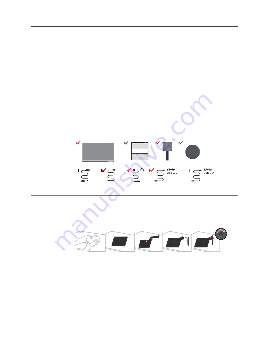
Shipping contents 

The product package should include the following items: 

Flat Panel Monitor

Information Flyer

Stand

Base

HDMI Cable(Optional)

DP Cable(Optional)

d

r

o

C

 r

e

 Pow

Notice for use 

To set up your monitor

please see the illustrations below. 

Note: 

Do not touch the monitor within the screen area. The screen area is glass and can be 

damaged by rough handling or excessive pressure. 

1. Carefully lay the monitor on a flat surface.
2. Put the stand and base to the monitor.

Note

: To attach a VESA mount

please see "Wall Mounting (Optional)"on page 2-10. 

Chapter 1.

 1-1 

HDMI

USB C-C Cable

DP

*: Depending on many factors such as the processingcapabilityof peri pheral devices, file 

attributes, and other factors related to system configuration and operating environments, the 

actual transfer rate using the various USB connectors on this device will vary and is typically 

slower thanthe data ratesas defined by the re spective USB specifications: - 5 Gbit/s for USB 

3.1 Gen 1; 10 Gbit/s for USB 3.1 Gen 2 & 20 Gbit/s for USB 3.2.

*

*

Summary of Contents for 61AE

Page 1: ...ThinkVision P24h 10 User Guide Machine Types 61AE ...

Page 2: ...ntal entities as commercial items as defined by 48 C F R 2 101 with limited and restricted rights to use reproduction and disclosure LIMITED AND RESTRICTED RIGHTS NOTICE If products data computer software or services are delivered pursuant a General Services Administration GSA contract use reproduction or disclosure is subject to restrictions set forth in Contract No GS 35F 05925 61AE GAR3 WW ...

Page 3: ...e 2 3 Using the direct access controls 2 3 Using the On Screen Display OSD controls 2 4 Selecting a supported display mode 2 8 Understanding power management 2 9 Caring for your monitor 2 10 Detaching the monitor base and stand 2 10 Wall Mounting Optional 2 10 Chapter 3 Reference information 3 1 Monitor specifications 3 1 Troubleshooting 3 3 Manually installing the monitor driver 3 5 Installing th...

Page 4: ...Safety information General Safety guidelines For tips to help you use your computer safely go to http www lenovo com safety Before installing this product read the Safety Information iii ...

Page 5: ...een area is glass and can be damaged by rough handling or excessive pressure 1 Carefully lay the monitor on a flat surface 2 Put the stand and base to the monitor Note To attach a VESA mount please see Wall Mounting Optional on page 2 10 Chapter 1 1 1 HDMI USB C C Cable DP Depending on many factors such as the processingcapabilityof peri pheral devices file attributes and other factors related to ...

Page 6: ...itions setting user controls and using the cable lock slot Types of adjustments Tilt Please see the illustration below for an example of the tilt range 5 Swivel With the built in pedestal you can tilt and swivel the monitor for the most comfortable viewing angle Chapter 1 1 2 R R ...

Page 7: ...n or lift up the monitor 110mm Monitor Pivot Adjust the screen position before rotating the monitor screen Make sure that the monitor screen ascent to its highest point and it inclines backward at 30 then rotate clockwise until the monitor stops at 90 Chapter 1 1 3 ...

Page 8: ... used to adjust the display For information on how to use these controls please see Adjusting your monitor image on page 2 3 Cable lock slot Your monitor is equipped with a cable lock slot located on the rear of your monitor in the lower position Chapter 1 1 4 DP DP ...

Page 9: ...g out this procedure 1 Power off your computer and all attached devices and unplug the computer power cord 2 Connect the cables according to below icon indication 3 For computer in HDMI connecting Note Lenovo recommends that customers who require to use the HDMI input on their monitor purchase the Lenovo HDMI to HDMI cable OB47070 www lenovo com support monitoraccessories Chapter 1 1 5 DP DP DP DP...

Page 10: ... who require to use the DP Cable on their monitor purchase the Lenovo DisplayPort to DisplayPort Cable 0A36537 www lenovo com support monitoraccessories Chapter 1 1 6 DP DP DP DP 5 For computer in USB Type C connecting DP DP If there are any you can consult the comments on page 5 ...

Page 11: ...6 Connect the speaker s audio cable and audio jack of monitor to transfer audio source from Note The audio output in DP MiniDP HDMI modes Chapter 1 1 7 DP Type C HDMI or USB ...

Page 12: ...rminal of the monitor and connect the other end of the USB cable to an appropriate USB port on your device Note The USB downstream port does not provide power while the monitor switch is off Chapter 1 1 8 If there are any you can consult the comments on page 5 ...

Page 13: ...nstallation and or equipment regulations shall be considered A certified power supply cord not lighter than ordinary polyvinyl chloride flexible cord according to IEC 60227 designation H05VV F 3G 0 75mm2 or H05VVH2 F2 3G 0 75mm2 shall be used Alternative a flexible cord be of synthetic rubber according to IEC 60245 designation H05RR F 3G 0 75mm2 shall be used 9 Connect the cables with cable clip C...

Page 14: ...tor for daisy chain on the monitor Note 1 Monitors sold in NA include an DP cable Note 2 For other regions Lenovo recommends that customers who require to use the Display Port input on their monitor purchase the Lenovo Display Port to Display Port cable 0A36537 For more information go to one of the following www lenovo com support monitoraccessories DP DP DP DP DP DP DP DP DP DP ...

Page 15: ...developing better ways to communicate with you Register your option on the following Web site http www lenovo com register Lenovo will send you information and updates on your registered product unless you indicate on the Web site questionnaire that you do not want to receive further information Chapter 1 1 11 13 When you install the monitor driver download the driver that corresponds to your moni...

Page 16: ... by considering the following items Recommended viewing distance between the eye and the monitor screen is 1 5 x the diagonal of the screen Solutions in meeting this required distance in cramped office situations include pulling desk away from wall or divider to make room for monitor using flat panel or compact displays placing the monitor in the desk corner or placing the keyboard in an adjustabl...

Page 17: ...office furniture to best suit your preferences now and as your preferences change over time Minor changes in posture can help avoid discomfort The longer you sit and work with your computer the more important it is to observe your working posture Avoid assuming any one posture for an extended period of time Periodically make minor modifications in your posture to help deter any discomforts that mi...

Page 18: ...xit Exit from menu Input Change Switches the video input source 2 Decrease Left Left browsing key For decreasing the value on adjustment bar tune inPress to move to last item Brightness Direct access to Brightness adjustment 3 Increase Up Right browsing key For increasing the value on adjustment bar tune in Press to move to next item 4 Menu To access OSD menu Press to confirm selection Press and h...

Page 19: ...u can move between options using or then press to select that function Use or to make adjustments Press to save to move backwards through the sub menus and exit from the OSD 3 Press 4 Press and hold for 10 seconds to lock the OSD This will prevent accidental adjustments to the OSD Press and hold for 10 seconds to unlock the OSD and allow adjustments to the OSD for 10 seconds to disable enable DDC ...

Page 20: ... h s i d d e R Bluish Custom Red Increases or decreases the saturation of red in the image Green Increases or decreases the saturation of green in the image Blue Increases or decreases the saturation of blue in the image Save Saves the custom color choices Input signal This monitor can accept video signals through three different connectors Most desktop computers use a analog connector Select digi...

Page 21: ...n only affects the language of the OSD It has no effect on any software running on the computer Menu Position Adjusts menu location Default Default returns the menu position to the default settings Custom Horizontal Changes the horizontal position of the OSD Vertical Changes the vertical position of the OSD Save Save the custom position choices Factory default Cancel Reset Low Blue Light Mode is r...

Page 22: ...ty Changes button repeat rate and menu time out settings Button repeat rate Off Default Slow Menu time out Set the duration of time that the OSD will remain active when no operation is performed All input ports Always on USB DP Select Select DP 1 1 or 1 2 DP 1 2 DP 1 1 DP Daisy Chain On Off Chapter 2 2 7 On Off ...

Page 23: ...ote If your system has previously been used with a CRT monitor and is currently configured to a display mode outside the range of this monitor you may need to reattach the CRT monitor temporarily until you have re configured the system preferably to 2560 x 1440 at 60 Hz which is the Native Resolution Display mode The display modes shown below have been optimized at the factory Table 2 3 Factory se...

Page 24: ...ng day or whenever you expect to leave it unused for long periods during the day Table 2 4 Power indicator State Power Indicator Screen Restoring Operation Compliance On Green Normal Standby Suspend Amber Blank Press a key or move the mouse There may be a slight delay before the image reappears Note Standby also occurs if there is no image output to the monitor ENERGY STAR Off Off Blank Press the ...

Page 25: ...o Lightly dampen a soft cloth with water and use this to gently wipe the covers and the screen Remove grease or finger marks with a damp cloth and a little mild detergent Detaching the monitor base and stand Step 1 Place the monitor on a soft and flat surface Step 2 Remove the base and stand from the monitor Wall Mounting Optional Refer to the instructions that come with the base mounting kit To c...

Page 26: ...ll mounting kit 100mm x100mm distance VESA Mounting Screw M4 x 10 mm VESA hole Step 5 Attach the LCD display to the wall following the instructions in the wall mounting kit For use only with UL Listed Wall Mount Bracket with minimum weight load 8kg Chapter 2 2 11 ...

Page 27: ...n Image Viewable image size 604 47mm 23 8 inch Maximum height 296 35mm 11 67 inch Maximum width 526 85mm 20 8inch Pixel pitch 0 2058mm 0 008 inch Power input Supply voltage 100 240V AC Max supply current 1 5A Power consumption Note Power consumption figures are for the monitor and the power supply combined Normal operation 67W max 24W typical Standby Suspend 0 5W Off 0 5W Video input DP Interface ...

Page 28: ... Clock frequency 300 MHz Communications VESA DDC CI Supported Display Modes Horizontal frequency 30 kHz 99 kHz Vertical frequency 50 Hz 76 Hz Native Resolution 2560 x 1440 at 60 Hz Temperature Operating 0 to 40 C 32 to 104 F Storage 20 to 60 C 4 to 140 F Shipping 20 to 60 C 4 to 140 F Humidity Operating 10 to 80 non condensing Storage 5 to 95 non condensing Shipping 5 to 95 non condensing Chapter ...

Page 29: ...e image quality is unacceptable The video signal cable is not connected with the monitor or system completely Be sure the signal cable is firmly plugged into the system and monitor Connecting and turning on your monitor on page 1 5 The color settings may be incorrect Select another color setting from the OSD menu Adjusting your monitor image on page 2 3 The power The monitor s Be sure the power Co...

Page 30: ...ls missing contact and Support on page discolored technology and is not an LCD defect the Support Center A 1 Fuzzy lines in text or a blurry image Horizontal or vertical lines through the image Image setup has not been optimized Your system Display Properties setting have not been optimized Adjust the resolution settings on your system to match the native resolution for this monitor 2560 x 1440 at...

Page 31: ...ed Settings icon 8 Click the Monitor tab 9 Click the Properties button 10 Click the Driver tab 11 Click Update Driver then click Browse the computer to find the driver program 12 Select Pick from the list of device driver program on the computer 13 Click the Hard Disk button By clicking the Browse button browse and point to the following path X Monitor Drivers Windows 7 where X indicates the folde...

Page 32: ... the driver program 12 Select Pick from the list of device driver program on the computer 13 Click the Hard Disk button By clicking the Browse button browse and point to the following path X Monitor Drivers Windows 10 where X indicates the folder in which the downloaded driver is located such as a desktop 14 Select the lenp24h 10 inf file and click the Open button Click the OK button 15 In the new...

Page 33: ...Appendix A A 1 Appendix A Service and Support Telephone technical support Country or Region Telephone Number China 400 810 6666 ...

Page 34: ...of the publication Lenovo may make improvements and or changes in the product s and or the program s described in this publication at any time without notice The products described in this document are not intended for use in implantation or other life support applications where malfunction may result in injury or death to persons The information contained in this document does not affect or chang...

Page 35: ...o in the United States other countries or both Lenovo The Lenovo logo ThinkCenter ThinkPad ThinkVision Microsoft Windows and Windows NT are trademarks of the Microsoft group of companies Other company product or service names may be trademarks or service marks of others ...

Page 36: ...Power cords and power adapters Use only the power cords and power adapters supplied by the product manufacturer Do not use the ac power cord for other devices Appendix B B 3 ...

Reviews: