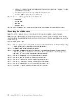
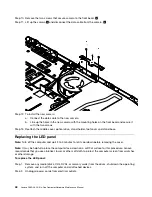


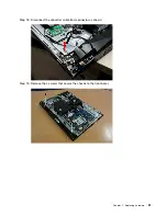
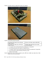

Step 22. Lift up the chassis to separate the chassis from the panel.
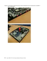
Step 23. To install the new the LED panel:
For two point touch model, the new LED panel
module including:
LED panel, touch cable, converter board cable
For five point touch model, the new LED panel
module including:
LED panel, touch control board, touch cable,
converter board cable
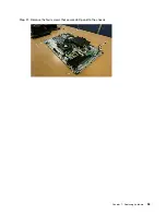
a.
Line up the chassis with new LED panel, and then place it into position.
b.
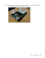
Secure the LED panel to the chassis with the four screws.
c.
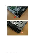
Line up the chassis and new LED panel with the front bezel, and then place it into position.
d.
Secure the chassis to the front bezel with the four screws.
e.
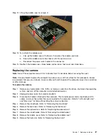
Reattach all the cables.
Step 24. Reattach the camera, heat-sink, speaker system, EMI cover, middle cover, optical drive, stand
holder, foot cover and stand base.
54
Lenovo C360–365 All-In-One ComputerHardware Maintenance Manual
Summary of Contents for 365
Page 2: ......
Page 6: ...iv Lenovo C360 365 All In One ComputerHardware Maintenance Manual ...
Page 8: ...2 Lenovo C360 365 All In One ComputerHardware Maintenance Manual ...
Page 16: ...10 Lenovo C360 365 All In One ComputerHardware Maintenance Manual ...
Page 18: ...12 Lenovo C360 365 All In One ComputerHardware Maintenance Manual ...
Page 24: ...18 Lenovo C360 365 All In One ComputerHardware Maintenance Manual ...


