background image

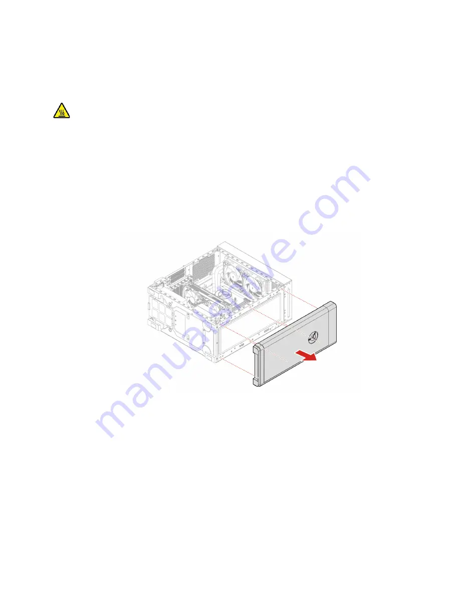
Front bezel

Prerequisite

Before you start, read 

Generic Safety and Compliance Notices

and print the following instructions.

Before you open the computer cover, turn off the computer and wait several minutes until the computer is 
cool.

Replacement procedure

1.  Turn off the computer and remove all connected devices and cables.

2.  Remove the power cord. See “Power cord” on page 14.

3.  Remove the left computer cover. See “Left computer cover” on page 15.

4.  Disconnect the top USB and audio assembly cable from the system board.

5.  Remove the front bezel.

Chapter 4

.

CRU replacement

19

Summary of Contents for 34IAZ7

Page 1: ...User Guide Lenovo Legion Tower 7i 34L 7 ...

Page 2: ... Warranty Guide Generic Safety and Compliance Notices Setup Guide First Edition August 2021 Copyright Lenovo 2021 LIMITED AND RESTRICTED RIGHTS NOTICE If data or software is delivered pursuant to a General Services Administration GSA contract use reproduction or disclosure is subject to restrictions set forth in Contract No GS 35F 05925 ...

Page 3: ...1 Chapter 4 CRU replacement 13 CRU list 13 Remove or replace a CRU 14 Power cord 14 Left computer cover 15 Right computer cover 17 Front bezel 19 3 5 inch storage drive 20 Storage drive rubber 22 2 5 inch storage drive for selected models 24 M 2 solid state drive 27 Memory module 29 Heat sink and fan assembly 30 PCI Express card and card holder 33 Coin cell battery 35 Power supply assembly 38 Chap...

Page 4: ...ii User Guide ...

Page 5: ...might not be available on your computer Depending on the version of the operating systems and programs some user interface instructions might not be applicable to your computer Documentation content is subject to change without notice Lenovo makes constant improvements to the documentation of your computer including this User Guide To get the latest documentation go to https pcsupport lenovo com M...

Page 6: ...iv User Guide ...

Page 7: ...Chapter 1 Meet your computer Front 1 Lenovo Legion logo Copyright Lenovo 2021 1 ...

Page 8: ...Top 1 USB 2 0 connectors 2 2 USB 3 2 connectors Gen 1 2 3 Headphone connector 4 Microphone connector 5 Power button 6 Dust Screen Related topics USB specifications on page 4 2 User Guide ...

Page 9: ...rs Gen 1 4 4 USB C 3 2 Gen 2 x 2 connector 5 Audio connectors 6 6 PCI Express card area 7 Power cord connector 8 USB 3 2 connector Gen 2 9 Ethernet connector 2 5G Related topics USB specifications on page 4 Work with Windows on page 7 Chapter 1 Meet your computer 3 ...

Page 10: ...hen press Enter Memory Double data rate 5 DDR5 unbuffered dual in line memory module UDIMM Storage device To view the storage drive capacity of your computer type disk management in the Windows search box and then press Enter Note The storage drive capacity indicated by the system is less than the nominal capacity Expansion 4 SATA3 Port 4 DDR5 UDIMM slots 3 M 2 solid state drive slots 2 Storage dr...

Page 11: ...2160 pixels 60 Hz Connect to USB C accessories to help expand your computer functionality To purchase USB C accessories go to https www lenovo com accessories Statement on USB transfer rate Depending on many factors such as the processing capability of the host and peripheral devices file attributes and other factors related to system configuration and operating environments the actual transfer ra...

Page 12: ...r common desktop computers From 40 C 40 F to 60 C 140 F For all in one desktop computers From 20 C 4 F to 60 C 140 F Relative humidity Operating 20 80 non condensing Storage 10 90 non condensing Altitude Operating 15 2 m 50 ft to 3048 m 10 000 ft Storage 15 2 m 50 ft to 12192 m 40 000 ft 6 User Guide ...

Page 13: ...computer to a wired network Airplane mode Airplane mode is a convenient setting to turn all wireless communications of your computer on and off You may need to turn it on when boarding an airplane Airplane mode Windows Updates Microsoft periodically releases feature and security updates to the Windows operating system Updates that are applicable to your Windows version are downloaded automatically...

Page 14: ...8 User Guide ...

Page 15: ...ed updates and fixes configure hardware settings and get personalized support Access Lenovo Vantage Type Lenovo Vantage in the search box and then press Enter To download the latest version of Lenovo Vantage go to Microsoft Store and search by the app name Key features Lenovo Vantage enables you to Know the device status easily and customize device settings Download and install UEFI BIOS firmware ...

Page 16: ... power plan 1 Type power plan in the Windows search box and then press Enter 2 Customize a power plan of your preference Transfer data Quickly share your files using the built in Bluetooth technology among devices with the same features You also can install a disc or media card to transfer data Connect to a Bluetooth enabled device for selected models You can connect all types of Bluetooth enabled...

Page 17: ...s and upgrades to help expand the capabilities of your computer Options include memory modules storage devices network cards power adapters keyboards mice and more To shop at Lenovo go to https pcsupport lenovo com warrantyupgrade Chapter 3 Explore your computer 11 ...

Page 18: ...12 User Guide ...

Page 19: ...e from Lenovo at any time upon request You might be required to return the defective part that is replaced by the CRU When return is required 1 return instructions a prepaid shipping label and a container will be included with the replacement CRU and 2 you might be charged for the replacement CRU if Lenovo does not receive the defective CRU within thirty 30 days of your receipt of the replacement ...

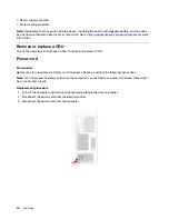
Page 20: ...des instructions on how to remove or replace a CRU Power cord Prerequisite Before you start read Generic Safety and Compliance Notices and print the following instructions Note Do not remove the power cord when the computer is connected to ac power Otherwise there might be a risk of short circuits Replacement procedure 1 Turn off the computer and remove all connected peripheral devices and cables ...

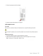
Page 21: ...he following instructions Before you open the computer cover turn off the computer and wait several minutes until the computer is cool Replacement procedure 1 Turn off the computer and remove all connected devices and cables 2 Hold the sides of the computer and gently lay it down so that the computer cover is facing up Note The side cover is made of glass Handle with care Chapter 4 CRU replacement...

Page 22: ... 4 Install the new computer cover and secure the cover with the screws 5 Place the computer in an upright position Then reconnect the power cord and all disconnected cables to the computer Note If a locking device is available use it to lock the computer 16 User Guide ...

Page 23: ...puter is cool Replacement procedure 1 Turn off the computer and remove all connected devices and cables 2 Place a soft clean towel or cloth on the desk or surface Hold the sides of your computer and gently lay it down so that the screen is against the surface and the computer cover is facing up 3 Remove the screws to remove the computer cover 4 Install the computer cover and secure it with screws ...

Page 24: ...5 Place the computer in an upright position Then reconnect the power cord and all disconnected cables to the computer Note If a locking device is available use it to lock the computer 18 User Guide ...

Page 25: ...d wait several minutes until the computer is cool Replacement procedure 1 Turn off the computer and remove all connected devices and cables 2 Remove the power cord See Power cord on page 14 3 Remove the left computer cover See Left computer cover on page 15 4 Disconnect the top USB and audio assembly cable from the system board 5 Remove the front bezel Chapter 4 CRU replacement 19 ...

Page 26: ... internal storage drive only for upgrade or repair The internal storage drive is not designed for frequent changes or replacement Before replacing the internal storage drive make a backup copy of all the data that you want to keep Do not touch the contact edge of the internal storage drive Otherwise the internal storage drive might get damaged Do not apply pressure to the internal storage drive Do...

Page 27: ...5 Remove the storage drive and the bracket 6 Remove the storage drive from the bracket Chapter 4 CRU replacement 21 ...

Page 28: ... 10 Reinstall all removed parts 11 Place the computer in an upright position Then reconnect the power cord and all disconnected cables to the computer Note If a locking device is available use it to lock the computer Storage drive rubber Prerequisite Before you start read Generic Safety and Compliance Notices and print the following instructions 22 User Guide ...

Page 29: ... 5 inch storage drive if any See 3 5 inch storage drive on page 20 5 Slide each storage drive rubber and pull away from storage drive bay 6 Insert each new storage drive rubber and secure into storage drive bay 7 Reinstall all removed parts Then reconnect the power cord and all disconnected cables to the computer Note If a locking device is available use it to lock the computer Chapter 4 CRU repla...

Page 30: ...that you want to keep Do not touch the contact edge of the internal storage drive Otherwise the internal storage drive might get damaged Do not apply pressure to the internal storage drive Do not make the internal storage drive subject to physical shocks or vibration Put the internal storage drive on a soft material such as cloth to absorb physical shocks Replacement procedure 1 Remove the power c...

Page 31: ...he storage drive into the bracket and secure it with screws 8 Install the storage drive and secure it with screw 9 Connect the signal cable and the power cable to the new storage drive Chapter 4 CRU replacement 25 ...

Page 32: ...ll removed parts 11 Place the computer in an upright position Then reconnect the power cord and all disconnected cables to the computer Note If a locking device is available use it to lock the computer 26 User Guide ...

Page 33: ...anges or replacement Before replacing the internal storage drive make a backup copy of all the data that you want to keep Do not touch the contact edge of the internal storage drive Otherwise the internal storage drive might get damaged Replacement procedure 1 Turn off the computer and remove all connected devices and cables 2 Remove the power cord See Power cord on page 14 3 Remove the right comp...

Page 34: ... Secure the M 2 solid state drive with the screw 10 Secure the thermal pad with screws to the M 2 solid state drive 11 Reinstall all removed parts 12 Place the computer in an upright position Then reconnect the power cord and all disconnected cables to the computer 28 User Guide ...

Page 35: ...allation order for memory modules shown in the following illustration Replacement procedure 1 Remove the power cord See Power cord on page 14 2 Remove the right computer cover See Right computer cover on page 17 3 Remove the front bezel See Front bezel on page 19 4 Disengage the latches and remove the memory module 5 Install the new memory module and secure the memory module with the latches Chapt...

Page 36: ...d Compliance Notices and print the following instructions The heat sink might be very hot Before you open the computer cover turn off the computer and wait several minutes until the computer is cool Replacement procedure 1 Remove the power cord See Power cord on page 14 2 Remove the right computer cover See Right computer cover on page 17 3 Remove the front bezel See Front bezel on page 19 4 Remov...

Page 37: ...6 Remove the screws to remove the heat sink 7 Install the heat sink and secure it with screws Chapter 4 CRU replacement 31 ...

Page 38: ...h screws 9 Reinstall all removed parts 10 Place the computer in an upright position Then reconnect the power cord and all disconnected cables to the computer Note If a locking device is available use it to lock the computer 32 User Guide ...

Page 39: ...ed devices and cables 2 Remove the left computer cover See Left computer cover on page 15 3 Remove the front bezel See Front bezel on page 19 4 Remove PCI Express card connector cable then remove two screws 5 Remove three screws and disengage the latch Then remove the PCI Express card and the holder from the computer 6 Remove two screws then remove the holder from PCI Express card Chapter 4 CRU re...

Page 40: ...to PCI Express card 8 Reinstall all removed parts 9 Install the PCI Express card and the holder to the computer 10 Secure the PCI Express card with the screws Then connect the PCI Express card connector cable 34 User Guide ...

Page 41: ... it Do not drop crush puncture the battery or make it subject to strong forces Battery abuse or mishandling can cause the battery to overheat which can cause gasses or flame to vent from the battery or coin cell battery Note To dispose of the coin cell battery refer to Lithium coin cell battery notice in the Safety and Warranty Guide Your computer has a special type of memory that maintains the da...

Page 42: ...Replacement procedure 1 Remove the right computer cover See Right computer cover on page 17 2 Disengage the latch 3 Remove the coin cell battery 4 Install the coin cell battery 36 User Guide ...

Page 43: ...ch 6 Reinstall all removed parts 7 Place the computer in an upright position Then reconnect the power cord and all disconnected cables to the computer Note If a locking device is available use it to lock the computer Chapter 4 CRU replacement 37 ...

Page 44: ...ng parts Keep fingers and other body parts away CAUTION Never remove the cover on a power supply or any part that has the following label attached Hazardous voltage current and energy levels are present inside any component that has this label attached There are no serviceable parts inside these components If you suspect a problem with one of these parts contact a service technician Replacement pr...

Page 45: ...5 Remove the power supply assembly mounting screw from the rear of the chassis 6 Remove the power supply assembly Chapter 4 CRU replacement 39 ...

Page 46: ... the rear of the chassis 9 Connect the power supply assembly cable into the system board 10 Reinstall all removed parts 11 Place the computer in an upright position Then reconnect the power cord and all disconnected cables to the computer Note If a locking device is available use it to lock the computer 40 User Guide ...

Page 47: ...y to drain out the liquid by turning over the computer If your computer has keyboard drainage holes on the bottom the liquid will be drained out through the holes Where can I get the latest device drivers and UEFI BIOS Lenovo Vantage or Lenovo PC Manager Lenovo Support Web site at https support lenovo com Self help resources Use the following self help resources to learn more about the computer an...

Page 48: ...and Warranty Guide Setup Guide This User Guide Regulatory Notice Go to https pcsupport lenovo com Then follow the on screen instructions to filter out the documentation you want Lenovo Support Web site with the latest support information of the following Drivers and software Diagnostic solutions Product and service warranty Product and parts details Knowledge base and frequently asked questions Go...

Page 49: ...ersion Which software applications were running at the time of the problem Can the problem be reproduced If so how 2 Record the system information Product name Machine type and serial number The following illustration shows where to find the machine type and serial number of your computer Lenovo Customer Support Center During the warranty period you can call Lenovo Customer Support Center for help...

Page 50: ...ller if authorized by Lenovo will make selected Engineering Changes ECs that apply to your hardware available Services not covered Replacement or use of parts not manufactured for or by Lenovo or nonwarranted parts Identification of software problem sources Configuration of UEFI BIOS as part of an installation or upgrade Changes modifications or upgrades to device drivers Installation and maintena...

Page 51: ...ht to improve and or modify the products and software programs described in the manuals included with your computer and the content of the manual at any time without additional notice The software interface and function and hardware configuration described in the manuals included with your computer might not match exactly the actual configuration of the computer that you purchase For the configura...

Page 52: ...enovo and is not covered by any open source license including any Linux agreement s which may accompany software included with this product Lenovo may update this document at any time without notice For the latest information or any questions or comments contact or visit the Lenovo Web site https pcsupport lenovo com Trademarks LENOVO and LENOVO logo are trademarks of Lenovo Intel Optane and Thund...

Page 53: ......

Page 54: ......

Reviews: