background image

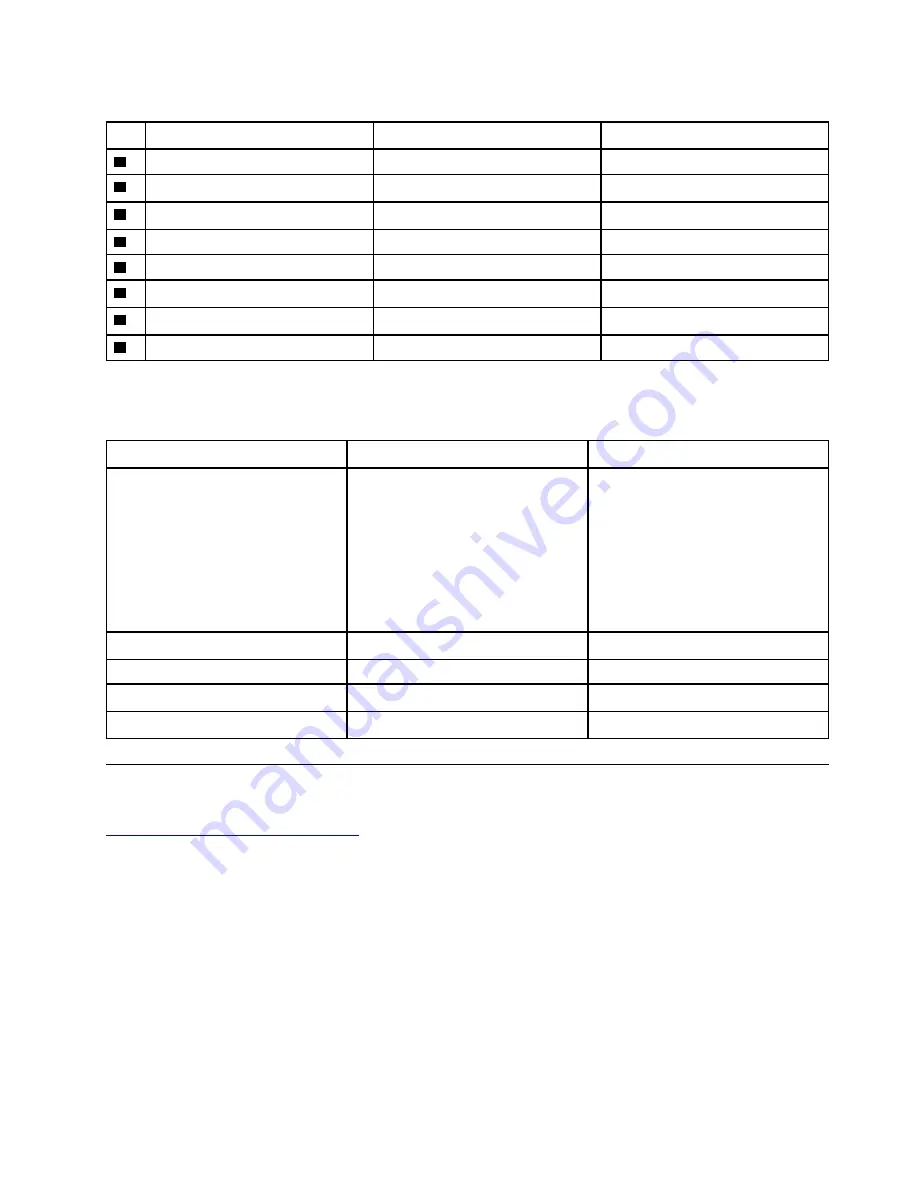
Table 4.  LCD FRUs and CRUs

No.

FRU description

Self-service CRU

Optional-service CRU

1

Screw rubbers

No

No

2

Strip cover

No

No

3

LCD panel

No

No

4

Front camera board

No

No

5

LCD cable

No

No

6

Hinges

No

No

7

Hinge rubbers

No

No

8

LCD base cover

No

No

Miscellaneous parts

Table 5.  Miscellaneous parts

FRU descriptions

Self-service CRU

Optional-service CRU

Screw pack: 

•  Screw M2 x L3, black (8)

•  Screw M2 x L2.5, black (8)

•  Screw M2 x L4, black (19)

•  Screw M2.5 x L5, black (6)

•  Screw M1.6 x L1.5, silver (3)

•  Screw M2.5 x L6, black (9)

No

No

ac power adapter

Yes

No

Power cord

Yes

No

Rubber pack

No

No

Thermalpad

No

No

Looking up FRU information

For detailed FRU information, including part numbers, descriptions, and substitution part numbers, go to: 

https://support.lenovo.com/partslookup

Chapter 4

.

Identifying FRUs (CRUs) 

31

Summary of Contents for 300e Chromebook 2nd Gen

Page 1: ...Hardware Maintenance Manual Lenovo 300e 500e Chromebook 2nd Gen ...

Page 2: ...Lenovo 2019 LIMITED AND RESTRICTED RIGHTS NOTICE If data or software is delivered pursuant to a General Services Administration GSA contract use reproduction or disclosure is subject to restrictions set forth in Contract No GS 35F 05925 ...

Page 3: ...Us 27 Locating FRUs and CRUs 27 Major FRUs and CRUs 28 LCD FRUs and CRUs 30 Miscellaneous parts 31 Looking up FRU information 31 Chapter 5 Removing a FRU or CRU 33 General guidelines 33 Cut off the power supply from the built in battery pack 33 Remove the Stylus Pen 34 Remove the lower case 34 Remove the battery pack 35 Remove the wireless module 37 Remove the speakers 38 Remove the power board 39...

Page 4: ...ii Hardware Maintenance Manual ...

Page 5: ... your computer Documentation content is subject to change without notice Lenovo makes constant improvements on the documentation of your computer including this Hardware Maintenance Manual To get the latest documentation go to https support lenovo com This documentation applies to the following product models Model name Machine type Lenovo 300e Chromebook 2nd Gen 81MB Lenovo 500e Chromebook 2nd Ge...

Page 6: ...iv Hardware Maintenance Manual ...

Page 7: ... other service technicians and the customer s personnel are not in a hazardous position Place removed covers and other parts in a safe place away from all personnel while you are servicing the machine Keep your tool case away from walk areas so that other people will not trip over it Do not wear loose clothing that can be trapped in the moving parts of a machine Make sure that your sleeves are fas...

Page 8: ...correctly and use the approved probe leads and accessories for that tester Stand on suitable rubber mats obtained locally if necessary to insulate you from grounds such as metal floor strips and machine frames Observe the special safety precautions when you work with very high voltages Instructions for these precautions are in the safety sections of maintenance information Use extreme care when me...

Page 9: ... or worn 4 Check for cracked or bulging batteries 5 Remove the cover 6 Check for any obvious non Lenovo alterations Use good judgment as to the safety of any non Lenovo alterations 7 Check inside the unit for any obvious unsafe conditions such as metal filings contamination water or other liquids or signs of fire or smoke damage 8 Check for worn frayed or pinched cables 9 Check that the power supp...

Page 10: ...battery operated system use an ESD common ground or reference point You can use coax or connector outside shells on these systems Use the round ground prong of the ac plug on ac operated computers Grounding requirements Electrical grounding of the computer is required for operator safety and correct system function Proper grounding of the electrical outlet can be verified by a certified electricia...

Page 11: ...DANGER DANGER DANGER DANGER DANGER DANGER Chapter 1 Safety information 5 ...

Page 12: ...6 Hardware Maintenance Manual ...

Page 13: ...PERIGO PERIGO Chapter 1 Safety information 7 ...

Page 14: ...PERIGO PERIGO PERIGO PERIGO PERIGO 8 Hardware Maintenance Manual ...

Page 15: ...PERIGO DANGER DANGER DANGER DANGER Chapter 1 Safety information 9 ...

Page 16: ...DANGER DANGER DANGER DANGER VORSICHT 10 Hardware Maintenance Manual ...

Page 17: ...VORSICHT VORSICHT VORSICHT VORSICHT Chapter 1 Safety information 11 ...

Page 18: ...VORSICHT VORSICHT VORSICHT 12 Hardware Maintenance Manual ...

Page 19: ...Chapter 1 Safety information 13 ...

Page 20: ...14 Hardware Maintenance Manual ...

Page 21: ...Chapter 1 Safety information 15 ...

Page 22: ...16 Hardware Maintenance Manual ...

Page 23: ...Chapter 1 Safety information 17 ...

Page 24: ...18 Hardware Maintenance Manual ...

Page 25: ...Chapter 1 Safety information 19 ...

Page 26: ...20 Hardware Maintenance Manual ...

Page 27: ...error does not recur do not replace the FRU Be careful not to replace a nondefective FRU What to do first When you return a FRU you must include the following information in the parts exchange form or parts return form that you attach to it 1 Name and phone number of service technician 2 Date of service 3 Date on which the machine failed 4 Date of purchase 5 Failure symptoms error codes appearing ...

Page 28: ... dropped or subject to excessive force Checking the ac power adapter If the computer fails only when the ac power adapter is used refer to the information in this topic to check the ac power adapter If the power on indicator does not turn on check the power cord of the ac power adapter for correct continuity and installation To check the ac power adapter do the following 1 Unplug the ac power adap...

Page 29: ...novo service credential is needed to download the image file Attention Make sure to download the latest version of the image file A shim created with an earlier version of the image file may cause the repair process to fail Step 3 Use a disk image tool to write the downloaded image to the USB drive An open source tool Win32 Disk Imager is available for download at http sourceforge net projects win...

Page 30: ... turned off If the GoogleRequiredTests fails refer to Common issues leading to GoogleRequiredTests fail on page 25 Note If any test is marked as failed the final process cannot be completed The final process can be forced to end by pressing the f key Do not force the final process to end when a component fails the test Force the final process to end only when the test has to be bypassed because it...

Page 31: ...caused by using unauthorized parts or missing parts If the write protect function is not turned off before recovering the computer with the repair shim it will also cause HWID mismatch Write protect function is off System cannot be finalized until the write protect function is turned back on Hardware identify A set of valid hardware identities HWIDs are provided by Google Google logs the exact har...

Page 32: ...26 Hardware Maintenance Manual ...

Page 33: ...n and replacement instructions are shipped with your product and are available from Lenovo at any time upon request You can find a list of CRUs for your product in this Hardware Maintenance Manual An electronic version of this manual can be found at https support lenovo com Click Documentation and then follow the on screen instructions to find the manual for your product Your computers contain the...

Page 34: ...Major FRUs and CRUs 1 2 3 6 7 9 8 10 12 11 4 5 13 14 15 Figure 1 300e 500e Chromebook 2nd Gen exploded view 28 Hardware Maintenance Manual ...

Page 35: ...le No No 2 Upper case with keyboard No No 3 System board No No 4 Bracket L No No 5 Speakers No No 6 Worldfacing camera No No 7 Wireless module No No 8 Straight power board cable No No 9 Power board No No 10 Bracket R No No 11 Curved power board cable No No 12 Front camera No No 13 Battery pack No No 14 Lower case No No 15 Stylus pen Yes No for selected models Chapter 4 Identifying FRUs CRUs 29 ...

Page 36: ...LCD FRUs and CRUs 1 2 3 4 5 6 7 8 Figure 2 LCD module exploded view 30 Hardware Maintenance Manual ...

Page 37: ...ts FRU descriptions Self service CRU Optional service CRU Screw pack Screw M2 x L3 black 8 Screw M2 x L2 5 black 8 Screw M2 x L4 black 19 Screw M2 5 x L5 black 6 Screw M1 6 x L1 5 silver 3 Screw M2 5 x L6 black 9 No No ac power adapter Yes No Power cord Yes No Rubber pack No No Thermalpad No No Looking up FRU information For detailed FRU information including part numbers descriptions and substitu...

Page 38: ...32 Hardware Maintenance Manual ...

Page 39: ...ent base cover DANGER Before removing any FRU or CRU shut down the computer and unplug all power cords from electrical outlets Attention After replacing a FRU do not turn on the computer until you have ensured that all screws springs and other small parts are in place and none are loose inside the computer Verify this by shaking the computer gently and listening for rattling sounds Metallic parts ...

Page 40: ... ac power adapter power supply from the built in battery pack will resume Remove the Stylus Pen Make sure the computer has been shut down before servicing the computer Step 1 Place the computer upside down on a flat surface Step 2 Pull out the Stylus pen from the pen slot Figure 3 Pull out the Stylus pen Refer to Major FRUs and CRUs on page 28 to look up details about the following replacement par...

Page 41: ...ry pack Make sure the following FRUs or CRUs have been removed Remove the Stylus Pen on page 34 Remove the lower case on page 34 Step 1 Detach the battery connector from the system board and then detach the power board cable connectors Figure 6 Detach cable connectors Attention Use your fingernail to unplug the connectors Do not pull the cable with force Step 2 Remove the curved power board cable ...

Page 42: ...Remove the 4 screws Screw specifications Number of screws M2 0 x 4 4 Step 4 Take out the battery pack Figure 9 Take out the battery pack Refer to Major FRUs and CRUs on page 28 to look up details about the following replacement part Battery pack 36 Hardware Maintenance Manual ...

Page 43: ... on page 34 Remove the battery pack on page 35 Step 1 Detach the main and auxiliary antenna cable connectors Figure 10 Detach the connectors Step 2 Remove 1 screw Figure 11 Remove 1 screw Screw specifications Number of screws M2 0 x 3 1 Step 3 Remove the wireless module by pulling it away from the slot Chapter 5 Removing a FRU or CRU 37 ...

Page 44: ...eakers Make sure the following FRUs CRUs have been removed Remove the Stylus Pen on page 34 Remove the lower case on page 34 Remove the battery pack on page 35 Step 1 Detach the speaker connector from the system board Figure 13 Detach the connector Step 2 Remove the 2 screws and then release the speaker cable from the cable guides 38 Hardware Maintenance Manual ...

Page 45: ...CRUs on page 28 to look up details about the following replacement parts speakers Remove the power board Make sure the following FRUs or CRUs have been removed Remove the Stylus Pen on page 34 Remove the lower case on page 34 Remove the battery pack on page 35 Step 1 Detach the power board cable connector from the system board Chapter 5 Removing a FRU or CRU 39 ...

Page 46: ...ve the 4 screws Screw specifications Number of screws M2 0 x 4 4 Step 3 Remove the power board and bracket Figure 18 Remove the power board and bracket Refer to Major FRUs and CRUs on page 28 to look up details about the following replacement parts 40 Hardware Maintenance Manual ...

Page 47: ...ge 37 Remove the speakers on page 38 Step 1 Detach the WorldFacing camera cable connector EDP cable connector keyboard cable connector and touchpad cable connector from the system board Note Not all 300e 500e Chromebook 2nd Gen SKUs include the WorldFacing camera cable Figure 19 Detach the connectors Step 2 Remove the 11 screws Figure 20 Remove the 11 screws Screw specifications Number of screws M...

Page 48: ...ollowing FRUs or CRUs have been removed Remove the Stylus Pen on page 34 Remove the lower case on page 34 Remove the battery pack on page 35 Remove the wireless module on page 37 Remove the speakers on page 38 Remove the system board on page 41 Step 1 Remove the sponge Then peel off the conductive fabric that secures the WorldFacing camera Figure 22 Remove the sponge and peel off the conductive fa...

Page 49: ...n detached from the system board The antenna cable connectors have been detached from the wireless module The following FRUs CRUs have been removed Remove the Stylus Pen on page 34 Remove the lower case on page 34 Remove the battery pack on page 35 Step 1 Remove the 6 screws that secure the hinges to the upper case Figure 24 Remove the 6 screws Screw specifications Number of screws M2 5 x 5 6 Step...

Page 50: ...onnector Otherwise the cables may be damaged Refer to Major FRUs and CRUs on page 28 to look up details about the following replacement part Upper case with keyboard Disassemble the LCD module The LCD module as a whole is not a FRU Instead it contains FRUs as its components Before disassembling the LCD module make sure it has been detached from the base cover Remove the LCD panel Step 1 Remove the...

Page 51: ...ep 2 Remove the 2 screws Figure 28 Remove the 2 screws Screw specifications Number of screws M2 0 x 3 2 Step 3 Carefully remove the strip cover Figure 29 Remove the strip cover Step 4 Remove the 3 screws Chapter 5 Removing a FRU or CRU 45 ...

Page 52: ...CD cable and antenna cables Figure 31 Remove the hinge rubbers Step 6 Push the LCD panel from top to bottom and then remove the LCD panel Figure 32 Remove the LCD panel Refer to LCD FRUs and CRUs on page 30 to look up details about the following replacement parts LCD module Screw rubber Strip cover 46 Hardware Maintenance Manual ...

Page 53: ...ve the battery pack on page 35 Remove the upper case with keyboard on page 43 Remove the LCD panel on page 44 Step 1 Turn over the LCD panel and then peel off the aluminum foil that secures the front camera Figure 33 Peel off the aluminum foil Step 2 Detach the front camera connector Figure 34 Detach the connector Step 3 Remove the front camera Chapter 5 Removing a FRU or CRU 47 ...

Page 54: ...igure 36 Detach the connectors Step 5 Remove the LCD cable Figure 37 Detach the connectors Refer to LCD FRUs and CRUs on page 30 to look up details about the following replacement parts Front camera LCD cable Remove the hinges Make sure the following FRUs or CRUs have been removed 48 Hardware Maintenance Manual ...

Page 55: ...Remove the front camera and the LCD cable on page 47 Step 1 Remove the 8 screws a a b b Figure 38 Remove the 8 screws Screw specifications Number of screws 1 M2 0 x 3 2 2 M2 0 x 2 5 6 Step 2 Remove the hinges Figure 39 Remove the hinges Refer to LCD FRUs and CRUs on page 30 to look up details about the following replacement parts Hinges LCD cover Chapter 5 Removing a FRU or CRU 49 ...

Page 56: ...50 Hardware Maintenance Manual ...

Page 57: ...Series features and connectors No Features and connectors 1 Front camera light 2 Front camera 3 Microphone 4 WorldFacing camera 5 WorldFacing camera light 6 Microphone 7 Power key 8 Security lock slot 9 USB C connector 10 USB 3 0 Type A connector 11 Power button and power light 12 Volume buttons 13 Stylus pen slot 14 Touchpad 15 Combo audio connector 16 microSD card slot Copyright Lenovo 2019 51 ...

Page 58: ...Table 6 300e 500e Chromebook 2nd Gen Series features and connectors continued 17 USB 3 0 Type A connector 18 dc in USB C connector 19 dc in light for selected models 52 Hardware Maintenance Manual ...

Page 59: ... region Label dimensions a Rating label and rating print label all 109 mm x 24 mm b W L label Argentina 68 mm x 6 mm c Adapter Label Argentina 65 mm x 20 mm d TW vision warning label Taiwan 70 mm x 10 mm e Indon SDPPI label Indonesia 15 mm x 10 mm f Indon rating label Indonesia 26 mm x 10 mm g US CA TW W L label Taiwan 32 mm x 10 mm US CA TW W L label US CA W L label Israel h India BIS label India...

Page 60: ...54 Hardware Maintenance Manual ...

Page 61: ...DMI and HDMI High Definition Multimedia Interface are trademarks or registered trademarks of HDMI Licensing LLC in the United States and other countries USB C is a trademark of USB Implementers Forum All other trademarks are the property of their respective owners 2019 Lenovo ...

Page 62: ......

Reviews: