When installing:
Make sure that the bezel is correctly oriented as shown in the following figure.
1030 Serial Ultrabay Slim device or travel bezel
For access, remove this FRU:
•
“1010 Battery pack” on page 66
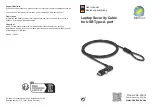
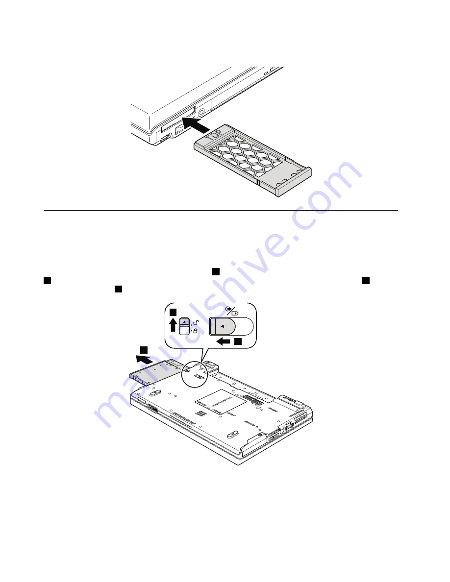
Removal steps of Serial Ultrabay Slim device or travel bezel
Holding the bay lock latch in the unlocked position
1
, slide the bay eject in the direction shown by arrow
2
, and then pull out the Ultrabay Slim device or the travel bezel in the direction shown by arrow
3
to
completely remove it
4
.
3
2
1
68
Hardware Maintenance Manual
Summary of Contents for 29577XU
Page 1: ...Hardware Maintenance Manual ThinkPad T410 and T410i ...
Page 6: ...iv Hardware Maintenance Manual ...
Page 11: ...DANGER DANGER DANGER DANGER DANGER Chapter 1 Safety information 5 ...
Page 12: ...DANGER 6 Hardware Maintenance Manual ...
Page 13: ...PERIGO PERIGO PERIGO Chapter 1 Safety information 7 ...
Page 14: ...PERIGO PERIGO PERIGO PERIGO PERIGO DANGER 8 Hardware Maintenance Manual ...
Page 15: ...DANGER DANGER DANGER DANGER DANGER Chapter 1 Safety information 9 ...
Page 16: ...DANGER DANGER VORSICHT VORSICHT VORSICHT 10 Hardware Maintenance Manual ...
Page 17: ...VORSICHT VORSICHT VORSICHT VORSICHT VORSICHT Chapter 1 Safety information 11 ...
Page 18: ...12 Hardware Maintenance Manual ...
Page 19: ...Chapter 1 Safety information 13 ...
Page 20: ...14 Hardware Maintenance Manual ...
Page 21: ...Chapter 1 Safety information 15 ...
Page 22: ...16 Hardware Maintenance Manual ...
Page 24: ...18 Hardware Maintenance Manual ...
Page 25: ...Chapter 1 Safety information 19 ...
Page 26: ...20 Hardware Maintenance Manual ...
Page 27: ...Chapter 1 Safety information 21 ...
Page 28: ...22 Hardware Maintenance Manual ...
Page 66: ...60 Hardware Maintenance Manual ...
Page 91: ...4 4 4 4 4 4 4 4 4 4 4 4 5 6 7 Chapter 8 Removing and replacing a FRU 85 ...
Page 128: ...122 Hardware Maintenance Manual ...
Page 130: ... FRUs marked with OP are available as options 124 Hardware Maintenance Manual ...
Page 131: ...Overall Chapter 10 Parts list 125 ...
Page 170: ...164 Hardware Maintenance Manual ...
Page 173: ......
Page 174: ...Part Number 63Y0535_05 Printed in 1P P N 63Y0535_05 63Y0535_05 ...