


Before servicing the computer
Carefully read this topic before servicing the computer.
Disabling the built-in battery
Before replacing any CRU, ensure that you disable Fast Startup first and then disable the built-in battery.
To disable Fast Startup, do the following:
1. Go to Control Panel, and then change the view of Control Panel from Category to Large icons or Small
icons.
2. Click
Power Options
, and then click
Choose what the power buttons do
on the left pane.
3. Click
Change settings that are currently unavailable
at the top.
4. If prompted by User Account Control (UAC), click
Yes
.
5. Clear the
Turn on fast startup
check box, and then click
Save changes
.
To disable the built-in battery, do the following:
1. Restart your computer. When the logo screen is displayed, immediately press F1 to enter ThinkPad
Setup.
2. Select
Config
➙
Power
. The
Power
submenu is displayed.
3. Select
Disable built-in battery
and press Enter.
4. Select
Yes
in the Setup Confirmation window. The built-in battery is disabled and the computer turns off
automatically. Wait three to five minutes to let the computer cool.
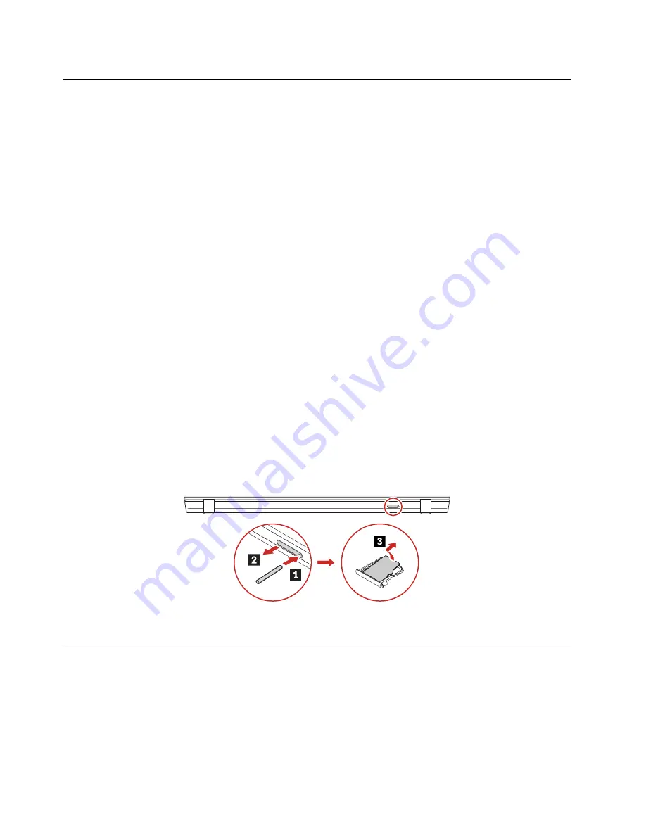
Removing the nano-SIM card and the nano-SIM-card tray
Some models you are servicing might have a nano-SIM card installed. If the computer you are servicing has
a nano-SIM card installed, remove the nano-SIM card and the nano-SIM-card tray before you start the
servicing.
After you finish the servicing, ensure that you install the card and the tray back into the slot firmly.
1010 Keyboard
Removal steps of the keyboard
Note:
If your replacement keyboard is not shipped with the special tool shown in the following illustrations,
you may use alternative pry tools to remove it.
70
T14 Gen 2 and P14s Gen 2 Hardware Maintenance Manual
Summary of Contents for 20VX
Page 1: ...T14 Gen 2 and P14s Gen 2 Hardware Maintenance Manual ...
Page 6: ...iv T14 Gen 2 and P14s Gen 2 Hardware Maintenance Manual ...
Page 11: ...DANGER DANGER DANGER DANGER DANGER DANGER Chapter 1 Safety information 5 ...
Page 12: ...DANGER 6 T14 Gen 2 and P14s Gen 2 Hardware Maintenance Manual ...
Page 13: ...PERIGO Chapter 1 Safety information 7 ...
Page 14: ...PERIGO PERIGO PERIGO PERIGO 8 T14 Gen 2 and P14s Gen 2 Hardware Maintenance Manual ...
Page 15: ...PERIGO PERIGO PERIGO DANGER DANGER Chapter 1 Safety information 9 ...
Page 16: ...DANGER DANGER DANGER DANGER DANGER 10 T14 Gen 2 and P14s Gen 2 Hardware Maintenance Manual ...
Page 17: ...DANGER VORSICHT VORSICHT VORSICHT VORSICHT Chapter 1 Safety information 11 ...
Page 18: ...VORSICHT VORSICHT VORSICHT VORSICHT 12 T14 Gen 2 and P14s Gen 2 Hardware Maintenance Manual ...
Page 19: ...Chapter 1 Safety information 13 ...
Page 20: ...14 T14 Gen 2 and P14s Gen 2 Hardware Maintenance Manual ...
Page 21: ...Chapter 1 Safety information 15 ...
Page 22: ...16 T14 Gen 2 and P14s Gen 2 Hardware Maintenance Manual ...
Page 23: ...Chapter 1 Safety information 17 ...
Page 24: ...18 T14 Gen 2 and P14s Gen 2 Hardware Maintenance Manual ...
Page 25: ...Chapter 1 Safety information 19 ...
Page 26: ...20 T14 Gen 2 and P14s Gen 2 Hardware Maintenance Manual ...
Page 30: ...24 T14 Gen 2 and P14s Gen 2 Hardware Maintenance Manual ...
Page 49: ...b LCD assembly Chapter 4 Related service information 43 ...
Page 50: ...44 T14 Gen 2 and P14s Gen 2 Hardware Maintenance Manual ...
Page 77: ...a b c d Chapter 8 Removing or replacing a FRU 71 ...
Page 104: ...98 T14 Gen 2 and P14s Gen 2 Hardware Maintenance Manual ...
Page 107: ...Removal steps of the LCD unit for Intel models Chapter 8 Removing or replacing a FRU 101 ...
Page 135: ......
Page 136: ...Part Number SP40W87698 Printed in China 1P P N SP40W87698 ...
Page 137: ... 1PSP40W87698 ...


