31
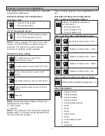
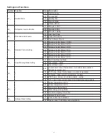
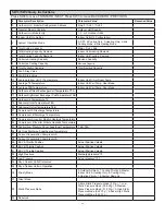
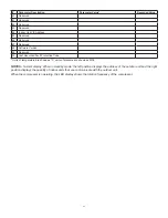
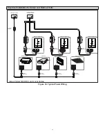
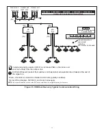
Figure 27. Mode Selection Box Wiring Diagrams
TRANSFORMER
TRANS3
Indoor No. 9
M-O
M-O
CN12
(CN13)
1(M-I) 2(M-I)
3(M-I) 4(M-I)
CN22
CN26
TRANS OUT
CN33
TRANS IN
CN32
SW1 SW2
DSP1 DSP2
EEV
A
CN18
T1C1
T2C2
CN24
Brown
Red
White
Blue
Brown
Red
White
Blue
Indoor No. 10
Indoor No. 11 Indoor No. 12
S1 S2
ON
SW3 SW4
ENC1 ENC2(2)
M-M M-M
CN14
(CN15)
CN15
(CN14)
P Q
P Q
P Q
P Q
CN34
TRANSFORMER
TRANS2
Indoor No. 5
M-O
M-O
CN12
(CN13)
1(M-I) 2(M-I)
3(M-I) 4(M-I)
CN22
CN26
TRANS OUT
CN33
TRANS IN
CN32
SW1 SW2
DSP1 DSP2
EEV
A
CN18
T1C1
T2C2
CN24
Brown
Red
White
Blue
Brown
Red
White
Blue
Indoor No. 6 Indoor No. 7 Indoor No. 8
S1 S2
ON
SW3 SW4
ENC1 ENC2(1)
M-M M-M
CN14
(CN15)
CN15
(CN14)
P Q
P Q
P Q
P Q
CN34
L1 L2
SVP
T1C1
Power in
To outdoor or MS units
communication bus
To indoor units communication bus
Outdoor
/
Upstream MS
Downstream MS
T2C2
Blue Red
Blue
Red
Green
Yellow
Gray
XT1
XS2
XS1
XP2
XP1
Gray
Yellow
Black
The wiring picture shown is for reference only
, actual product may vary
.
Guide for main control panel dial code
ENC1
MS control box address
(Field setting, the first PCB setting is required
and unique from other MS box.)
CODE
NAME
XT1
Terminal block
XS1
~
XS2
Connectors
XP1
~
XP2
Connectors
T1C1
~
T2C2
Temperature sensor
SV#A-X, SV#B-X
SVP
EEVA
Electronic expansion valve
Solenoid valve
TRANS1
~
TRANS3 Transformer
P Q
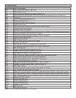
DSP1 and DSP2 display content
E3
Communication error between first PCB to the other PCBs
in the same MS box
Outlet of plate exchanger(subcooler) error
E4
Inlet of plate exchanger(subcooler) error
H0
Communication error between MS box to master outdoor unit
E2
Green
LL
S1/S2 setting is not consistent to communication wiring
MS PCB address
(Factory setting, can’t be changed.
0 means the first PCB, 1 means the second
PCB, 2 means the third PCB)
ENC2
P Q
CN13
(CN12)
POWER
CN17
SV1B-1 SV2B-2 SV3B-3 SV4B-4
SV1A-1 SV2A-2 SV3A-3 SV4A-4
CN9
SVP
Yellow
Black
Yellow
Black
Yellow
Black
Yellow
Black
CN4
SV4
CN3
SV3
CN5
SV2
CN6
SV1
CN16
POWER
CN17
SV1B-5 SV2B-6 SV3B-7 SV4B-8
SV1A-5 SV2A-6 SV3A-7 SV4A-8
CN9
SVP
Yellow
Black
Yellow
Black
Yellow
Black
Yellow
Black
CN4
SV4
CN3
SV3
CN5
SV2
CN6
SV1
CN16
POWER
CN17
SV1B-9 SV2B-10 SV3B-11 SV4B-12
SV1A-9 SV2A-10 SV3A-11 SV4A-12
CN9
SVP
Yellow
Black
Yellow
Black
Yellow
Black
Yellow
Black
CN4
SV4
CN3
SV3
CN5
SV2
CN6
SV1
CN16
EEVA
Blue Red
Blue Red
Red
Blue
TRANSFORMER
TRANS1
Indoor No. 1
M-O
M-O
CN12
(CN13)
1(M-I) 2(M-I)
3(M-I) 4(M-I)
CN22
CN26
TRANS OUT
CN33
TRANS IN
CN32
SW1 SW2
DSP1 DSP2
EEV
A
CN18
T1C1
T2C2
CN24
Brown
Red
White
Blue
Brown
Red
White
Blue
Indoor No. 2 Indoor No. 3 Indoor No. 4
S1 S2
ON
SW3 SW4
ENC1 ENC2(0)
M-M M-M
CN14
(CN15)
CN15
(CN14)
P Q
P Q
P Q
P Q
CN34
CN13
(CN12)
CN13
(CN12)
X1
X2
●
S1: 11 means synchronous control for 2 ports
(First PCB is port 1 and 2, Second PCB is port 5 and 6, third PCB is port 9 and 10)
●
S2: 11 means synchronous control for 2 ports
(First PCB is port 3 and 4, Second PCB is port 7 and 8, third PCB is port 11 and 12)
S1/S2
ON
(00 is default)
LIGHTER
LIGHTER
LIGHTER
Piping Line
Control Wiring NOTE:
Outdoor Unit
NO.1 MS Unit
MS-Indoor
MS-Outdoor or MS
Indoor
NO.1
Indoor
NO.2
Indoor
NO.3
Indoor
NO.4
Outdoor
Indoor Unit
NO.2
NO.2 MS Unit
MS-Indoor
Indoor
NO.1
Indoor
NO.2
Indoor
NO.3
Indoor
NO.4
Downstream MS
Piping & Communication Cable Connection
NO.2 MS Unit
NO.1 MS Unit
6 5 4 3 2 1
Indoor Unit
NO.3
Indoor Unit
NO.1
6 5 4 3 2 1
(P Q )
(P Q )
(P Q )
(P Q )
(P
Q )
(P
Q )
NO.3 MS Unit
6 5 4 3 2 1
NO.3 MS Unit
MS-Indoor
Indoor
NO.1
Indoor
NO.2
Indoor
NO.3
Indoor
NO.4
MS-MS
Upstream MS Downstream MS
(P
Q )
Indoor control wiring must match with indoor piping connection.
ENC1(2)
ENC1(1)
ENC1(0)
MS-MS
Upstream MS Downstream MS
Summary of Contents for VPB Series
Page 47: ...47...


