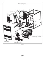
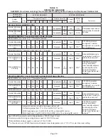
Lennox SL280DF060NV36B Unit Information Download Page 14

Page 14

TABLE 5 Continued

Code

Diagnostic Codes/Status of Equipment

Action Required to Clear and Recover
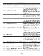
E271

Soft lockout - Exceeded maximum number of re

-

tries. Last retry failed due to the pressure switch 

opening.

Check pressure (inches w.c.) of low pressure switch clos-

ing on heat call. Measure operating pressure (inches w.c.). 

Inspect vent and combustion air inducer for correct oper-

ation and restriction. Clears when heat call finishes suc

-

cessfully.

E272

Soft lockout - Exceeded maximum number of re

-

cycles. Last recycle due to the pressure switch 

opening.

Check operation of low pressure switch to see if it is stuck 

closed on heat call. Check pressure (inches w.c.) of high 

pressure switch closing on heat call. Measure operating 

pressure (inches w.c.). Inspect vent and combustion air 

inducer for correct operation and restriction. Clears when 

heat call finishes successfully.

E273

Soft lockout - Exceeded maximum number of re

-

cycles. Last recycle due to flame failure.

Check micro-amperes of flame sensor using control diag

-

nostics  or  field-installed  mode.  Clean  or  replace  sensor. 

Measure voltage of neutral to ground to ensure good unit 

ground. Clears when heat call finishes successfully.
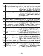
E274

Soft lockout - Exceeded maximum number of re

-

cycles. Last recycle failed due to the limit circuit 

opening or limit remained open longer than 3 min

-

utes

Shut down system. 1-hour soft lockout. Check firing rate 

and  air  flow.  Check  for  blockage.  Clears  when  heat  call 

finishes successfully.

E275

Soft lockout - Flame sensed out of sequence. 

Flame signal is gone.

Shut off gas. Check for gas valve leak. 1-hour soft lockout. 

Clears when flame has been proven stable.

E276

Watchguard calibration failure.

Unable to perform pressure switch calibration. Check vent 

system and pressure switch wiring connections. 1-hour soft 

lockout. Clears when calibration has finished successfully.

E290

Ignitor circuit fault - Failed ignitor or triggering cir-

cuitry.

Measure resistance of hot surface ignitor. Replace if open 

or  not  within  specifications.  1-hour  soft  lockout.  Clears 

when flame has been proven stable.

E291

Heat air flow restricted below the minimum.

Check for dirty filter and air flow restriction. Check blower 

performance. 1-hour soft lockout. Cleared when heat call 

finishes successfully.

E292

Indoor blower motor unable to start due to ob-

structed wheel, seized
bearings.

Indoor blower motor unable to start (seized bearing, stuck 

wheel, etc.). Replace motor or wheel if assembly does not 

operate or meet performance standards. 1-hour soft lock-

out. Clears after circulator successfully starts.

E294

Combustion air inducer over current.

Check combustion blower bearings, wiring and amps. Re-

place if does not operate or does not meet performance 

standards. Clears after inducer current is sensed to be in-

range after the ignition following the soft lockout or reset.

E295

Indoor blower motor temperature is too high.

Indoor blower motor over temperature (motor tripped on 

internal protector). Check motor bearings and amps. Re-

place if necessary. Cleared after blower demand is satis-

fied.

E310

Discharge error temperature sensor failure. Only 

shown if shorted or
out of range.

Compare outdoor sensor resistance to temperature/ re-

sistance charts in installation instructions. Replace sensor 

if  necessary.  Cleared  in  Communicating  mode:  30  sec

-

onds after fault recovered. In Non- Communicating mode: 

Cleared after the current heat call is completed.

E311

Heat rate reduced to match indoor blower air flow.

Warning Only. Furnace blower in cutback mode due to 

restricted airflow. Reduce firing rate every 60 seconds to 

match  available  CFM.  Check  filter  and  duct  system.  To 

clear, replace filter if needed or repair/ add duct. 2-stage 

controls  will  reduce  firing  rate  to  1st  stage.  Clears  when 

heat call finishes successfully.

Summary of Contents for SL280DF060NV36B

Page 1: ...es of 60 000 to 80 000 Btuh and cooling applications up to 5 tons Refer to Engineering Handbook for proper sizing SL280DFNV model units are equipped with a communi cating enabled SureLight two stage v...

Page 2: ...otection 15 15 Shipping Data lbs 1 package 123 145 NOTE Filters and provisions for mounting are not furnished and must be field provided 1 Annual Fuel Utilization Efficiency based on DOE test procedur...

Page 3: ...minimum 380 cfm Lennox Smart Zoning System Applications Minimum blower speed is 380 cfm SL280DF060NV36B BLOWER MOTOR WATTS COOLING 1 Cooling Speed DIP Switch Settings Motor Watts Various External Stat...

Page 4: ...1380 1575 1575 1800 2000 2270 Factory Default 990 1110 1250 1440 1400 1600 1820 2050 890 995 1135 1300 1270 1435 1635 1855 1 Cooling and heating speeds are based on a combination of DIP switch settin...

Page 5: ...Control box Flue chase Internal flue pipe assembly Blower assembly Blower assembly Heat exchanger assembly Air fuel intake assembly Gas valve Combustion air inducer Access panel Parts Arrangement FIG...

Page 6: ...noperable simply replace entire control Can cause injury or death Unsafe operation will result if repair is attempted 4 Integrated Control A92 Units are equipped with the communicating enabled Sure Li...

Page 7: ...ners will always fire on first stage heat The combustion air in ducer will operate on low speed and indoor blower will operate on low heat speed The unit will switch to second stage heat after a recog...

Page 8: ...ST STAGE T STAT R CLASS 2 VOLTAGE TO THERMOSTAT G MANUAL FAN FROM T STAT C THERMOSTAT SIGNAL GROUND CONNECTED TO TRANSFORMER GRD TR CHASIS GROUND GRD Y1 THERMOSTAT 1ST STAGE COOL SIGNAL Y2 THERMOSTAT...

Page 9: ...OFF OPTION B OFF 82 100 OFF OPTION C OFF 100 100 OFF OPTION D OFF 100 OFF DEFAULT 10 10 HIGH SPEED MEDIUM HIGH SPEED MEDIUM LOW SPEED LOW SPEED 7 PROTECTIVE PLASTIC FILM ON DIP SWITCHES MAY BE REMOVED...

Page 10: ...the flame signal mode The integrated control will display the flame current on 7 segment LED in in micro amps uA Flame signal mode is exited after any of the follow ing Power is reset Pressing and hol...

Page 11: ...ect Alarm clears 5 seconds after fault recovered E111 Low line voltage Reverse line power voltage wiring System resumes normal operation 5 seconds after fault recovered E112 Ground not detected System...

Page 12: ...ture will be set as installed and that could be seen in About screen In normal operation after control recognizes sensors alarm will be sent if valid temperature reading is lost To get rid of setting...

Page 13: ...tion and restriction Resumes normal operation after fault is cleared E227 Low pressure switch open during trial for ignition or run mode Check pressure inches w c of low pressure switch closing on hea...

Page 14: ...hour soft lockout Clears when calibration has finished successfully E290 Ignitor circuit fault Failed ignitor or triggering cir cuitry Measure resistance of hot surface ignitor Replace if open or not...

Page 15: ...tween R O on integrated control with non communicating outdoor unit Dual fuel module required for heat pump application Configuration link R to O needs to be restored Replace link or hard wire Applica...

Page 16: ...tory set in the OFF position which provides a 7 minute delay before second stage heat is initiated If the switch is toggled to the ON position it will provide a 12 minute delay before second stage hea...

Page 17: ...nutes mo tor runs at 100 until demand is satisfied Once demand is met motor ramps down to stop OFF OFF 82 CFM 100 CFM COMPRESSOR DEMAND 7 1 2 MIN Ramping Option C Motor runs at 100 until demand is sat...

Page 18: ...integrated control W915 must be cut if two stage cooling will be used If the Y1 to Y2 link is not cut the outdoor unit will operate in second stage cooling only TABLE 12 OPERATING SEQUENCE SL280DFV N...

Page 19: ...allowing the room space to maintain a cooler room thermostat setpoint ROOM THERMOSTAT CALLS FOR FIRST AND SECOND STAGE COOLING BASIC MODE only active on a Y1 thermostat demand Normal Operation 1 On O...

Page 20: ...sor which monitors varying conditions inside the motor such as motor workload BLOWER MOTOR COMPONENTS STATOR WINDINGS BEARING ROTOR FIGURE 7 The controller uses sensing devices to sense what posi tion...

Page 21: ...ximately 5 minutes to discharge when the dis connect is opened For this reason it is necessary to wait at least 5 minutes after turning off power to the unit before attempting to service motor Power C...

Page 22: ...Line Voltage Connector J49 4 Pin Control Connector J48 5 Pin J49 4 Pin FIGURE 8 BLOWER B3 HARNESS CONNECTORS MOTOR with INTEGRATED CONTROLLER SHAFT P49 4 Pin P48 5 Pin P48 5 Pin P49 4 Pin J48 Connecto...

Page 23: ...Measure the resistance between each of the three motor leads 3 pin plug and the unpainted part of the end shield If the winding resistance to ground is 100k ohms re place the motor and control module...

Page 24: ...et and outlet pressure taps are located on the valve A regulator adjustment screw is located on the valve 4 Thermal Switch The auto reset switch is located on the front of the in take air elbow The sw...

Page 25: ...e 25 HEATING COMPONENTS Air Gas Plenum Burner Gasket Orifice Housing Gas Valve Air Orifice Sensor Ignitor Gas Orifice Thermal Switch location Intake Air Screen Intake Air Elbow Coupling O Ring FIGURE...

Page 26: ...then then there is a problem with the wiring between the jack plug and control If the reading is not correct the issue is the ignitor Meter set to ohms Test 3 Insert meter probes into the terminals 1...

Page 27: ...f the combustion air inducer is not operating or if the flue becomes obstructed On heat demand first or second stage the switch senses that the combustion air inducer is operating It closes a circuit...

Page 28: ...gas line Turning Off Gas To Unit 1 Set thermostat to lowest setting 2 Turn off all electrical power to unit if service is to be performed 3 Remove access panel 4 Move switch on valve to OFF Do not fo...

Page 29: ...r measurements have been taken E Proper Gas Flow Approximate Furnace should operate at least 5 minutes before check ing gas flow Determine time in seconds for two revolu tions of gas through the meter...

Page 30: ...ws corresponding steps with the steps below 1 Turn off the electrical power and gas supply to the furnace 2 Remove the air hose fitting from the brass fitting on the air inlet screen 3 Use a 5 16 nut...

Page 31: ...compare to TABLE 21 The maximum carbon monoxide reading should not exceed 100 ppm TABLE 21 Firing Rate CO2 For Natural CO2 For LP High Fire 6 0 7 8 7 5 9 9 Low Fire H High Altitude Units may be instal...

Page 32: ...signal Pressure Signal pressure within range Replace gas valve Check the following 1 Vent air intake pipe restriction 2 Plugged air inlet screen 3 Signal hoses to gas valve for kinks loose fit or plug...

Page 33: ...TEMPERATURE RISE Supply Duct Temperature Return Duct Temperature _ Temperature Rise FIGURE 22 C External Static Pressure 1 Tap locations shown in FIGURE 23 2 Punch a 1 4 diameter hole in supply and re...

Page 34: ...ir inducer and clean if necessary 8 Evaluate the heat exchanger integrity by inspecting the heat exchanger per the AHRI heat exchanger inspection procedure This procedure can be viewed at www ahrinet...

Page 35: ...ally inspect inside the burner for any blockage caused by foreign matter Remove any blockage FIGURE 25 shows burner detail Replace gasket between burner plate and air fuel plenum then re install burne...

Page 36: ...age 36 Flue chase Internal flue pipe assembly Gas valve Combustion air inducer Heat Exchanger and Burner Air Fuel Plenum Burner Re install screws per the numbered sequence shown Gasket Gasket FIGURE 2...

Page 37: ...ontacts The control also checks for S102 high heat and S128 low heat prove switch normally open contacts Once self check is complete and all safety switches are operational heat call can continue NOTE...

Page 38: ...is satisfied the gas valve is de energized and the field selected indoor blower off delay begins The combustion air inducer begins a 5 second post purge period 9 When the combustion air post purge pe...

Page 39: ...STAGE OPERATION Communicating Integrated Control Communicating Thermostat Outdoor Unit nace air handler control and four wires between the outdoor unit and the furnace air handler control When a ther...

Page 40: ...W Gh Gs Cf HVAC EQUIP DEHUMIDIFIER CONTROL HVAC EQUIPMENT DH 24V IN JUMPER COMMUNICATING ENABLED FURNACE COMMUNICATING ENABLED FURNACE ICOMMUNICATING THERMOSTAT CONVENTIONAL NON COMMUNICATING SYSTEM C...

Page 41: ...NOX COMMUNICATING THERMOSTAT OR DAMPER CONTROL MODULE CONVENTIONAL TERMINALS FLOAT SWITCH LENNOX COMMUNICATING INDOOR UNIT CONVENTIONAL OUTDOOR UNIT 1 OR 2 STAGE LENNOX COMMUNICATING FURNACE EL296V SL...

Page 42: ...NOT CUT ANY ON BOARD LINKS S1 T STAT FURNACE TERM STRIP OUTDOOR UNIT 1 Heat 2 Cool NOTE Use DIP switch 2 to set second stage heat ON delay OFF 7 minutes ON 12 minutes ON CUT ON BOARD LINK W915 2 STAG...

Page 43: ...TAGE COMPR S1 T STAT FURNACE TERM STRIP OUTDOOR UNIT 2 Heat 2 Cool with t stat with humidity control OFF CUT ON BOARD LINK W915 2 STAGE COMPR CUT ON BOARD LINK W914 DEHUM OR HARMONY S1 T STAT FURNACE...

Page 44: ...ARD LINK W951 HEAT PUMP T STAT FURNACE TERM STRIP HEAT PUMP 67M41 Y H L Y2 D B L Y2 T T outdoor sensor Dual Fuel Two Stage Heat Pump ComfortSense thermostat w bilities Capable of 2 stage gas heat cont...

Page 45: ...LINK W914 DEHUM OR HARMONY T STAT FURNACE TERM STRIP HEAT PUMP 67M41 Y H L Y2 D B L Y2 T T outdoor sensor Dual Fuel Two Stage Heat Pump ComfortSense thermostat w bilities Capable of 2 stage gas heat m...

Page 46: ...for 10 second period During that period press and hold push button for 5 seconds Integrated control will store code in memory and will automatically exit Program Unit Capacity Size Mode and reset If s...

Page 47: ...S H S I OFF NO INDUCER OFF AFTER POST PURGE HARD LOCKOUT ERROR CODE FLASHES YES YES YES 1 2 1 LOW PRESSURE SWITCH OPENS 1 2 HARD LOCKOUT REQUIRES THERMOSTAT RESET OR CYCLING OF POWER TO RESET THE LOCK...

Page 48: ...FOR 1ST REQUEST FOR 2ND STAGE HEAT YES CALL FOR HEAT SATISFIED INDUCER SWITCHED TO HIGH SPEED SINGLE STAGE THERMOSTAT 2 STAGE THERMOSTAT NO INDUCER SWITCHED TO LOW SPEED 5 MINUTE DELAY ERROR CODE FLA...

Page 49: ...AGE CALL FOR HEAT SATISFIED NO YES DE ENERGIZE 2ND STAGE GAS VALVE INDUCER SPEED SWITCHED TO LOW SPEED 1 2 3 1ST STAGE HEAT 1ST STAGE CALL FOR HEAT SATISFIED NO YES GAS VALVE DE ENERGIZED INDUCER OFF...

Page 50: ...PROFILES THE SPECIFIC PROFILE IS SELECTED USING THE 1 1 2 2 1 1 1 2 2 DE ENERGIZE 1ST STAGE COOLING CONTACTOR COMPRESSOR FAN 2ND STAGE COOLING REQUEST STILL ACTIVE COOLING REQUEST STILL ACTIVE CALL F...

Page 51: ...FOR HEAT RECEIVED REQUEST FOR COOLING RECEIVED GO TO CALL FOR 1ST STAGE HEAT YES GO TO CALL FOR COOLING 1 1 1 4 YES NO CALL FOR FAN INDOOR BLOWER ON CONTINUOUS FAN SPEED MAINTAIN INDOOR BLOWER AT CON...

Reviews: