Page 7
XP15 SERIES
REMOVE 4 SCREWS TO REMOVE PANEL FOR
ACCESSING COMPRESSOR AND CONTROLS.
INSTALL BY POSITIONING PANEL WITH HOLES
ALIGNED; INSTALL SCREWS AND TIGHTEN.
Figure 11. Access Panel
Detail A
Detail C
Detail B
ROTATE IN THIS DIRECTION;
THEN DOWN TO REMOVE PANEL
SCREW
HOLES
LIP
IMPORTANT! DO NOT ALLOW
PANELS TO HANG ON UNIT BY
TOP TAB. TAB IS FOR ALIGNMENT
AND NOT DESIGNED TO SUPPORT
WEIGHT OF PANEL.
PANEL SHOWN SLIGHTLY
ROTATED TO ALLOW TOP TAB TO
EXIT (OR ENTER) TOP SLOT FOR
REMOVING (OR INSTALLING)
PANEL.
Figure 12. Removing/Installing Louvered Panels
(Detail A, B and C)
WARNING
Unit must be grounded in accordance
with national and local codes.
Electric Shock Hazard. Can cause
injury or death.
Line voltage is present at all
components when unit is not in
operation on units with single-pole
contactors. Disconnect all remote
electric power supplies before
opening access panel. Unit may have
multiple power supplies.
MAINTAIN MINIMUM PANEL ANGLE (AS CLOSE TO PARALLEL WITH THE UNIT
AS POSSIBLE) WHILE INSTALLING PANEL.
PREFERRED ANGLE
FOR INSTALLATION
Detail D
ANGLE MAY BE TOO
EXTREME
HOLD DOOR FIRMLY ALONG
THE HINGED SIDE TO MAINTAIN
FULLY−ENGAGED TABS
Figure 13. Removing/Installing Louvered Panels
(Detail D)
ACCESS PANEL
Removal and reinstallation of the access panel is
illustrated in figure 11.
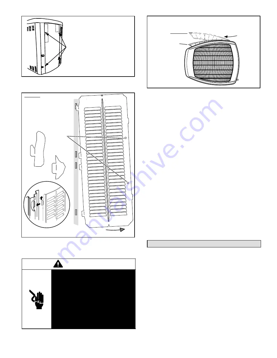
LOUVERED PANELS
Remove the louvered panels as follows:
1. Remove two screws, allowing the panel to swing open
slightly.
2.
Hold the panel firmly throughout this procedure.
Rotate bottom corner of panel away from hinged
corner post until lower three tabs clear the slots as
illustrated in figure 12, detail B.
3. Move panel down until lip of upper tab clears the top
slot in corner post as illustrated in figure 12, detail A.
Position and Install Panel
Position the panel almost
parallel with the unit as illustrated in figure 13, detail D with
the screw side as close to the unit as possible. Then, in a
continuous motion:
S
Slightly rotate and guide the lip of top tab inward as
illustrated in figure 12, details A and C; then upward
into the top slot of the hinge corner post.
S
Rotate panel to vertical to fully engage all tabs.
S
Holding the panel’s hinged side firmly in place, close
the right−hand side of the panel, aligning the screw
holes.
When panel is correctly positioned and aligned, insert the
screws and tighten.
Electrical Connections
In the U.S.A., wiring must conform with current local codes
and the current National Electric Code (NEC). In Canada,
wiring must conform with current local codes and the current
Canadian Electrical Code (CEC).
ELECTRICAL AND CONTROL CONNECTIONS
Refer to the furnace or blower coil installation instructions
for additional wiring application diagrams and refer to unit
nameplate for minimum circuit ampacity and maximum
overcurrent protection size.
NOTE − Connect conduit to the unit using a proper conduit
fitting. Units are approved for use only with copper
conductors. A complete unit wiring diagram is located on
the back side of the unit’s access panel.
NOTE − For proper voltages, select thermostat wire gauge
per the following chart:


