background image

Page 6

I-UNIT COMPONENTS

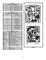
Unit  components  are  shown  in  figure  1.The  gas  valve, 

combustion air inducer and burners can be accessed by 

removing the upper access panel. Electrical components 

are in the control box (figure 2) found in the blower section.

ELECTROSTATIC DISCHARGE (ESD)

Precautions and Procedures

 CAUTION

Electrostatic  discharge  can  affect 

electronic components. Take precautions 

to neutralize electrostatic charge by 

touching your hand and tools to metal 

prior to handling the control.

1. Control Transformer (T1)

A transformer located in the control box provides power to
the low voltage section of the unit. Transformers on all
models are rated 40VA with a 120V primary and a 24V 

secondary.

2. Door Interlock Switch (S51)

A door interlock switch rated 14A at 125VAC is wired in 

series with line voltage. When the blower door is removed 

the unit will shut down.

NOTE - 

The door interlock switch is a safety switch. Do 

not by-pass or jumper switch.

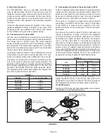
      CONTROL BOX

DOOR INTERLOCK

SWITCH (S51)

INTEGRATED CONTROL

(A92)

TRANSFORMER

(T1)

CIRCUIT

BREAKER

(CB8)

FIGURE 2 

3. Circuit Breaker (CB8)

A 24V circuit breaker is also located in the control box. The 

switch  provides  overcurrent  protection  to  the  transform

-

er (T1). The breaker is rated at 3A at 32V. If the current 

exceeds this limit the breaker will trip and all unit opera

-

tion will shutdown. The breaker can be manually reset by 

pressing the button on the face.

4. Integrated Control (A92)

103217-03 & 107163-01

 WARNING

Shock hazard.

Disconnect power before servicing. Control is not 

field  repairable.  If  control  is  inoperable,  simply 

replace entire control.

Can cause injury or death. Unsafe operation will 

result if repair is attempted.

The hot surface ignition control system consisting of an 
integrated control (figure 3 with control terminal designa

-

tions in tables 1, 2 and 3), sensor and ignitor (figure 6). 
The integrated control and ignitor work in combination to 
ensure furnace ignition and ignitor durability. The integrat

-

ed control, controls all major furnace operations. The inte

-

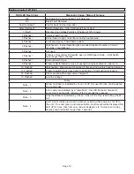
grated control also features a RED LED for troubleshoot

-

ing and two accessory terminals rated at (1) one amp. The 
nitride  ignitor  is  made  from  a  non-porous,  high  strength 
proprietary  ceramic  material  that  provides  long  life  and 
trouble free maintenance.

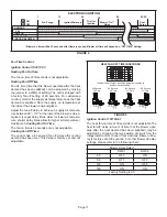
Electronic Ignition (Figure 4)

On a call for heat the integrated control monitors the com

-

bustion  air  inducer  pressure  switch. The  control  will  not 
begin  the  heating  cycle  if  the  pressure  switch  is  closed 
(bypassed).  Once  the  pressure  switch  is  determined  to 
be open, the combustion air inducer is energized. When 
the differential in the pressure switch is great enough, the 
pressure  switch  closes  and  a  15-second  pre-purge  be

-

gins. If the pressure switch is not proven within 2-1/2 min

-

utes,  the  integrated  control  goes  into  Watchguard-Pres

-

sure Switch mode for a 5-minute re-set period.
After the 15-second pre-purge period, the ignitor warms 
up for 20 seconds during which the gas valve opens at 
19 seconds for a 4-second trial for ignition. The ignitor re

-

mains energized for the first 3 seconds during the 4 second 
trial. If ignition is not proved during the 4-second period, 
the integrated control will try four more times with an inter 
purge  and  warm-up  time  between  trials  of  35  seconds. 
After a total of five trials for ignition (including the initial 
trial), the integrated control goes into Watchguard-Flame 
Failure mode. After a 60-minute reset period, the integrat

-

ed control will begin the ignition sequence again.

Summary of Contents for ML180DF045E36A

Page 1: ...LP Propane operation ML180DFE model units are equipped with a hot surface ignition system and a constant torque ECM motor The motor is programmed to provide constant torque at each of the five select...

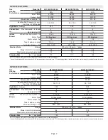
Page 2: ...Utilization Efficiency based on DOE test procedures and according to FTC labeling regulations Isolated combustion system rating for non weatherized furnaces SPECIFICATIONS Gas Heating Performance Mode...

Page 3: ...s cfm Watts cfm Watts 0 00 1430 285 1215 180 1035 120 995 110 930 100 0 10 1400 285 1175 185 995 130 885 100 850 90 0 20 1375 300 1145 200 950 140 840 110 725 85 0 30 1335 315 1120 210 915 145 790 115...

Page 4: ...1195 130 0 10 1725 390 1495 270 1390 220 1320 195 1145 140 0 20 1695 405 1470 285 1340 235 1280 210 1105 145 0 30 1660 415 1425 300 1290 240 1225 215 1040 160 0 40 1615 430 1395 310 1250 255 1185 230...

Page 5: ...Box includes integrated control interlock switch and transformer Gas Valve Burner Box includes sensor ignitor and rollout switches Combustion Air Inducer Blower Access Panel Heating Compartment Acces...

Page 6: ...t if repair is attempted The hot surface ignition control system consisting of an integrated control figure 3 with control terminal designa tions in tables 1 2 and 3 sensor and ignitor figure 6 The in...

Page 7: ...lve Out TABLE 3 1 4 Quick Connect Terminals 120HUM Humidifier 120VAC LINE 120VAC XFMR Transformer 120VAC CIRC Indoor blower 120VAC EAC Indoor air quality accessory 120VAC NEUTRALS Common 120VAC HUM24...

Page 8: ...Switch Open 9 Pressure Switch failed to close or opened during heat demand 10 Watchguard Pressure Switch opened 5 times during one heat demand 11 Pressure Switch stuck closed prior to activation of c...

Page 9: ...llout Switch Open 9 Pressure Switch failed to close or opened during heat demand 10 Watchguard Pressure Switch opened 5 times during one heat demand 11 Pressure Switch stuck closed prior to activation...

Page 10: ...s2 Pressure Switch failed to close or opened during heat demand inducer on 10 Flashes2 Watchguard Pressure switch opened 5 times during a single heating demand 11 Flashes2 Pressure switch stuck closed...

Page 11: ...zed Longer delay times allow for lower air tempera ture shorter delay times allow for higher air temperature See figure 5 Cooling Fan On Time The fan on time is 2 seconds and is not adjustable Cooling...

Page 12: ...thin three minutes or SureLight control will go into Watchguard for one hour The switch is factory set and cannot be adjusted The switch may have a different setpoint for each unit model number If lim...

Page 13: ...ire from Integrated Control and Connect Alligator Clip to Flame Sensor Lead Flame Sensor Terminal Remove Sensor Wire from Integrated Control and Connect Alligator Clip to Terminal on Control DIGITAL M...

Page 14: ...needed If the reading on the meter is not correct 0 or infinity then a second test is needed Test 2 Check ignitor for correct resistance Seperate the 2 pin jack plug near the manifold and check resist...

Page 15: ...ducer Pressure Switch S18 Units are equipped with a combustion air pressure switch located on the combustion air inducer orifice bracket The switch is connected to the combustion air inducer housing b...

Page 16: ...resent in tests 1 and 2 and motor is not operating properly replace motor The motor is not field repairable If replacing the indoor blower motor or blower wheel is necessary placement is critical The...

Page 17: ...peed tap used for continuous fan 1 2 3 4 or 5 on input plug P49 If 24 volts is not present problem may be up stream of plug P49 Proceed to test 4 Multi Meter set to VAC 12 0 12 0 24 Multi Meter set to...

Page 18: ...ximately the same resistance within an ohm 3 Check to see if the blower wheel spins freely Motor Test FIGURE 16 TABLE 9 Scale Measurement range in words ohms 2 M two megohm two million ohms 0 2 000 00...

Page 19: ...to be performed 3 Remove the upper access panel 4 Move gas valve switch to OFF position Do not force See figure 18 5 Replace the upper access panel B Safety or Emergency Shutdown Disconnect main powe...

Page 20: ...itting Connect to a test gauge to measure supply pressure 2 Start unit and allow 5 minutes for unit to reach steady state 3 After allowing unit to stabilize for 5 minutes record supply pressure and co...

Page 21: ...opane 10 0 10 0 10 0 11 0 13 0 TABLE 13 Pressure Switch and Gas Conversion Kits at all Altitudes Model Input Size High Altitude Pressure Switch Kit High Altitude Natuarl Gas Orifice Kit LP Propane Ori...

Page 22: ...132 Vac NOTE Figures 21 and 22 are typical ignition control illustrations CHECK VOLTAGE BETWEEN LINE NEUTRAL AND LOW VOLTAGE C TERMINAL FIGURE 20 TABLE 14 Furnace Status Measurement VAC Expected Maxi...

Page 23: ...5 W C For cooling speed external static pressure drop must not be more than 0 8 W C 4 Seal the hole when the check is complete EXTERNAL STATIC PRESSURE Supply Duct Static Return Duct Static Total Duct...

Page 24: ...rovide combustion air 10 Inspect the furnace venting system to make sure it is in place structurally sound and without holes corrosion or blockage Vent system must be free and clear of obstructions an...

Page 25: ...manifold assembly to the vestibule panel and remove the assembly from the unit 7 Remove screws from both sides top and bottom of vestibule panel 8 Remove heat exchanger It may be necessary to spread c...

Page 26: ...burner box cover 15 Reconnect all wires 16 Reconnect top cap and vent pipe to combustion air inducer outlet 17 Reconnect gas supply piping 18 Turn on power and gas supply to unit 19 Set thermostat and...

Page 27: ...e found to be closed Call for heat can continue 5 A92 integrated control energizes B6 combustion air inducer S18 combustion air pressure switch closes Once S18 closes a 15 second pre purge follows 6 A...

Page 28: ...OFF COMBUSTION AIR INDUCER ON INDOOR BLOWER ON HEATING SPEED LED FLASHES CODE 11 PRESSURE SWITCH CLOSED GAS VALVE OFF COMBUSTION AIR INDUCER OFF INDOOR BLOWER OFF WITH DELAY Sequence holds until press...

Page 29: ...NCE FOUR TIMES FLAME SIGNAL 1 5 MICROAMPS OR GREATER YES YES YES ROLLOUT SWITCH CLOSED LED FLASHES CODE 8 ROLLOT SWITCH OPEN GAS VALVE POWER OFF COMBUSTION AIR INDUCER POWER ON INDOOR BLOWER ON SEQUEN...

Page 30: ...SLOW FLASH RATE REMAINS UNCHANGED THROUGHOUT COOLING CYCLE THERMOSTAT CALLS FOR COOLING COMPRESSOR CONTACTOR AND SYSTEM FAN ENERGIZED WITH 2 SECOND DELAY COOLING SPEED EAC TERM ENERGIZED COMPRESSOR O...

Page 31: ...D EAC TERM REMAINS ON THERMOSTAT OPENS MANUAL FAN SELECTION MADE AT THERMOSTAT CONTROL G ENERGIZES SYSTEM FAN AT FAN SPEED EAC TERM ENERGIZED NO YES YES NO SYSTEM FAN SWITCHES TO HEAT SPEAD AFTER 30 S...

Reviews: