Page 10
Brazing Connection Procedure
1 − Cut ends of the refrigerant lines square (free from nicks
or dents). Debur the ends. The pipe must remain
round, do not pinch end of the line.
2 − Before making line set connections, use dry nitrogen to
purge the refrigerant piping. This will help to prevent
oxidation and the introduction of moisture into the sys-
tem.
3 − Use silver alloy brazing rods (5 or 6 percent minimum
silver alloy for copper−to−copper brazing or 45 percent
silver alloy for copper−to−brass or copper−to−steel braz-
ing) which are rated for use with HCFC−22 refrigerant.
Wrap a wet cloth around the valve body and the copper
tube stub. Braze the line set to the service valve.
4 − Wrap a wet cloth around the valve body and copper
tube stub to protect it from heat damage during braz-
ing. Wrap another wet cloth underneath the valve body
to protect the base paint.
NOTE − The tube end must stay bottomed in the fitting
during final assembly to ensure proper seating, sealing
and rigidity.
5 − Install a field−provided thermal expansion valve (ap-
proved for use with HCFC−22 refrigerant) in the liquid
line at the indoor coil.
Refrigerant Metering Device
H27 units are used in expansion valve systems only. See
the Lennox Engineering Handbook for approved TXV
match-ups and application information.
Expansion valves equipped with Chatleff fittings are avail-
able from Lennox. Refer to the Engineering Handbook for
applicable expansion valves for use with specific match-
ups.
If you install an expansion valve with an indoor coil that
includes a fixed orifice, remove the orifice before instal-
ling the expansion valve.
IMPORTANT
Failure to remove RFC orifice when installing an ex-
pansion valve on the indoor coil will result in improp-
er operation and damage to the system.
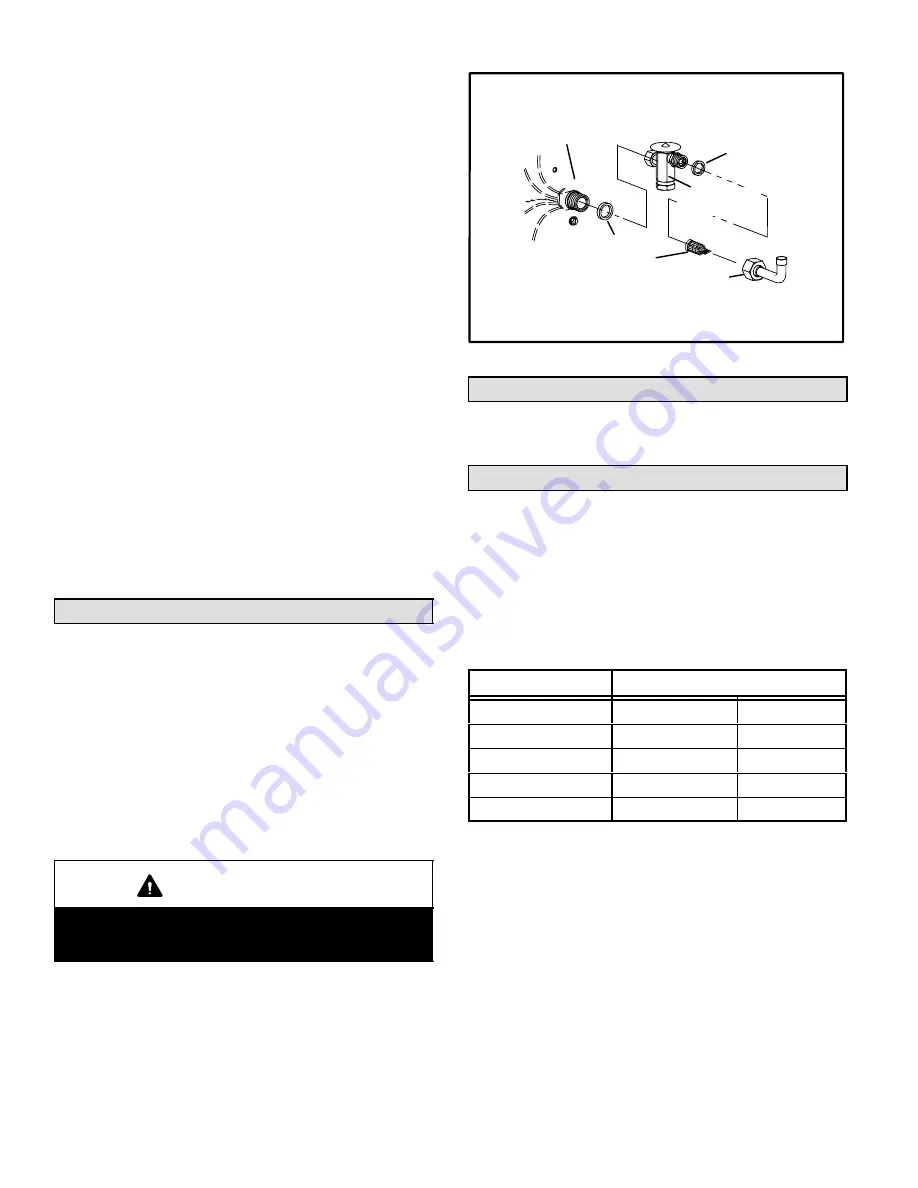
See figure 10 for installation of the check expansion valve.
Metering Device Installation
expansion
valve
o−ring
o−ring
strainer
liquid line
stub
distributor
Figure 10
Manifold Gauge Set
When checking the unit charge, use a manifold gauge set
that is equipped with low loss" hoses. Do not use a man-
ifold gauge set with anything other than a low loss" hose.
Service Valves
The liquid line and vapor line service valves (figures 11 and
12) and gauge ports are used for leak testing, evacuating,
charging and checking charge. See table 2 for torque re-
quirements.
Each valve is equipped with a service port which has a fac-
tory−installed Schrader valve. A service port cap protects
the Schrader valve from contamination and serves as the
primary leak seal.
Table 2
Torque Requirements
Part
Recommended Torque
Service valve cap
8 ft.− lb.
11 NM
Sheet metal screws
16 in.− lb.
2 NM
Machine screws #10
28 in.− lb.
3 NM
Compressor bolts
90 in.− lb.
10 NM
Gauge port seal cap
8 ft.− lb.
11 NM
To Access Schrader Port:
1 − Remove the service port cap with an adjustable wrench.
2 − Connect gauge to the service port.
3 − When testing is complete, replace the service port cap.
Tighten finger tight, then an additional 1/6 turn.
To Open Service Valve:
1 − Remove stem cap with an adjustable wrench.
2 − Use a service wrench with a hex−head extension to
back the stem out counterclockwise as far as it will go.


