Page 13
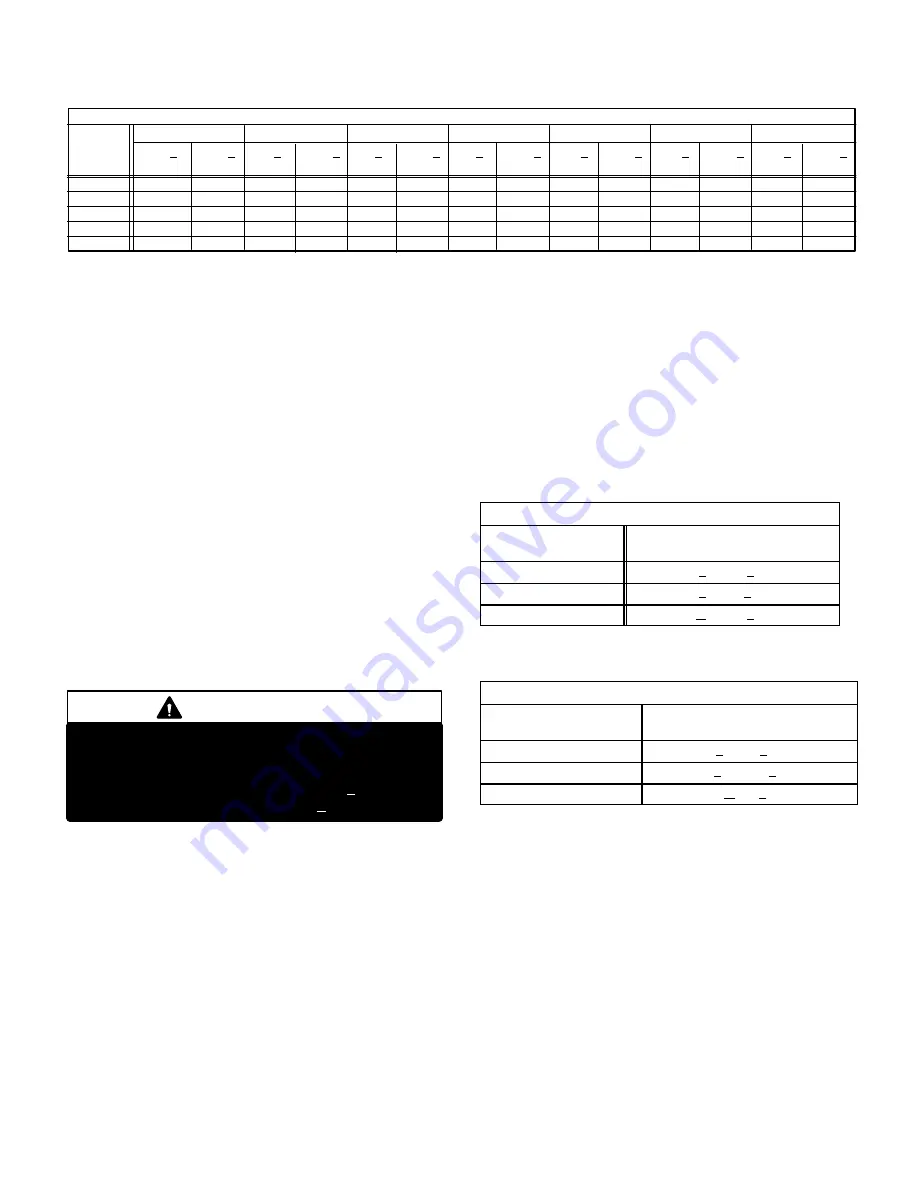
TABLE 10 (Late Models)
OUTDOOR
TEMP. (
_
F)
75
76
77
78
79
142
167
194
223
256
Suct.+
5 psig
Liq.+
10 psig
65
75
85
95
105
76
77
78
79
80
143
168
196
226
260
Suct.+
5 psig
Liq.+
10 psig
72
73
74
76
77
139
163
191
223
255
Suct.+
5 psig
Liq.+
10 psig
70
71
72
73
75
138
164
192
223
256
Suct.+
5 psig
Liq.+
10 psig
74
75
76
78
79
141
166
186
227
261
Suct.+
5 psig
Liq.+
10 psig
71
72
73
75
77
130
156
175
216
251
Suct.+
5 psig
Liq.+
10 psig
73
74
75
76
77
171
196
225
232
251
Suct.+
5 psig
Liq.+
10 psig
HS26−018
HS26−024
HS26−030
HS26−036
HS26−042
HS26−048
HS26−060
NORMAL OPERATING PRESSURES
If the system is completely void of refrigerant, the recom
mended and most accurate method of charging is to weigh
the refrigerant into the unit according to the total amount
shown on the unit nameplate. Also refer to the SPECIFI
CATIONS tables on page 1 for early model HS26 units and
page 2 for late model HS26 units.
If weighing facilities are not available or if unit is just low on
charge, the following procedure applies.
The following procedures are intended as a general guide
for use with expansion valve systems only. For best re
sults, indoor temperature should be between
70
°
F and 80
°
F. Outdoor temperature should be 60
°
F or
above. Slight variations in charging temperature and pres
sure should be expected. Large variations may indicate a
need for further servicing.
APPROACH METHOD (TXV SYSTEMS)
(Ambient Temperature of 60
_
F [16
_
C] or Above)
1− Connect gauge manifold. Connect an upright HCFC22
drum to center port of gauge manifold.
IMPORTANT
The following procedure requires accurate read
ings of ambient (outdoor) temperature, liquid tem
perature and liquid pressure for proper charging.
Use a thermometer with accuracy of +2
°
F and a
pressure gauge with accuracy of +5 PSIG.
2− Record outdoor air (ambient) temperature.
3− Operate indoor and outdoor units in cooling mode. Allow
units to run until system pressures stabilize.
4− Make sure thermometer well is filled with mineral oil be
fore checking liquid line temperature.
5− Place thermometer in well and read liquid line tempera
ture. Liquid line temperature should be a few degrees
warmer than the outdoor air temperature. Tables 11 and
12 show how many degrees warmer the liquid line tem
perature should be.
Add refrigerant to make the liquid line cooler.
Recover refrigerant to make the liquid line warmer.
TABLE 11
APPROACH METHOD − EXPANSION VALVES SYSTEM
MODEL
Liquid Line
_
F (
_
C) Warmer Than
Outside Ambient Temperature
H2−26−261,311
3 + 1 (1.6 + .5)
HS26−411
4 + 1 (2.2 + .5)
HS26−461
6 + 1 (3.3 + .5)
TABLE 12
APPROACH METHOD − EXPANSION VALVES SYSTEMS
MODEL
Liquid Line
_
F (
_
C) Warmer Than
Outside Ambient Temperature
HS26−036, 048
5 + 1 (2.8 + .5)
HS26−018, 030, 042, 060
8 + 1 (4.44 + .5)
HS26−024
9 + 1 (5+ .5)
6− When unit is properly charged liquid line pressures
should approximate those in table 9 or table 10.
D−Oil Charge
Refer to Table 1 and 2 on page 6.


