Page 12
TABLE 4
KIT
CONTENTS
TUBE SHELF LIFE
10N46 − Refrigerant Analysis
Checkmate−RT700
10N45 − Acid Test Tubes
Checkmate−RT750A (three pack)
2 − 3 years @ room temperature. 3+
years refrigerated
10N44 − Moisture Test Tubes
Checkmate − RT751 Tubes (three
pack)
6 − 12 months @ room temperature. 2
years refrigerated
74N40 − Easy Oil Test Tubes
Checkmate − RT752C Tubes (three
pack)
2 − 3 years @ room temperature. 3+
years refrigerated
74N39 − Acid Test Kit
Sporlan One Shot − TA−1
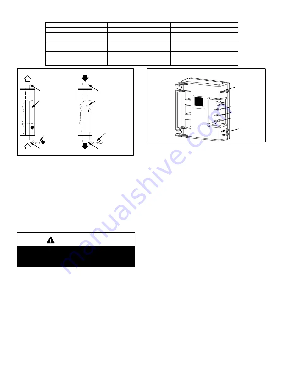
FIGURE 18
CHARGE COMPENSATOR OPERATION
During cooling mode, the va-
por line is hotter than the liq-
uid line. Stored liquid is
heated (boiled) and forced
back into circulation.
During heating mode, the va-
por line is cooler than the liq-
uid line. Excess refrigerant is
forced into the charge com-
pensator where it condenses
and collects.
Vapor Line
(To Outdoor Coil)
Vapor Line
(From Compressor Discharge Port)
Vapor Line
(From Outdoor Coil)
Vapor Line
(To Compressor Suction Port)
Stored Liquid
To Liquid Line
To be Circulated
Through Indoor Coil
Excess Refrigerant
To be Condensed and Stored
as Liquid
Compensator Tank
Compensator Tank
COOLING MODE
HEATING MODE
V−Lennox System Operation Monitor (A132)
The Lennox system operation monitor (LSOM) is a 24 volt
powered module wired directly to the indoor unit . See diag-
nostic module A132 on wiring diagram and figure 19. The
LSOM is located in the control box and is used to trouble
shoot problems in the system. The module has three LED’s
for troubleshooting: GREEN indicates power status, YEL-
LOW indicates an abnormal condition and RED indicates
thermostat demand, but compressor not operating. See
table 5 for troubleshooting codes.
IMPORTANT
The LSOM is not a safety component and cannot
shut down or control the HPXA19. The LSOM is a
monitoring device only.
W−Crankcase Heater (HR1)
Compressors in all units are equipped with a 70 watt belly-
band type crankcase heater. HR1 prevents liquid from ac-
cumulating in the compressor. HR1 is controlled by the
crankcaseheater thermostat.
X− Crankcase heater Thermostat (S40)
Thermostat S40 controls the crankcase heater in all units.
S40 is located on the liquid line. When liquid line tempera-
ture drops below 50° F the thermostat S40 closes energizing
HR1. The thermostat will open, de−energizing HR1 once liq-
uid line temperature reaches 70° F .
FIGURE 19
System Operation Monitor
Y
C
R
LE
D
LED’s
Y−Defrost System
The demand defrost controller uses basic differential tem-
perature means to detect when the system performs poor-
ly because of ice build−up on the outdoor coil. The control-
ler also uses self−calibrating" principles to calibrate itself
when the system starts and after every time the system
defrosts. The control board has the following compo-
nents: defrost relays, anti−short cycle timed−off control,
pressure switch/safety control, 5−trip lockout circuit, test
mode pins, ambient and coil temperature sensors, field
selectable termination temperature pins, and a field low
voltage connection terminal strip. See figure 20.
The control monitors ambient temperature, outdoor coil
temperature and total run time to determine when a de-
frost cycle is required. Two temperature probes are per-
manently attached to the control. The coil temperature
probe is designed with a spring clip to allow mounting to
the outside coil tubing. The location of the coil sensor is
important for proper defrost operation. See figure 21 for
coil sensor location. The ambient temperature sensor is
located in the PVC tube next to the filter drier.
NOTE − The logic of the demand defrost board accurately
measures the performance of the system as frost accumu-
lates on the outdoor coil. This typically will translate into
longer running time between defrost cycles as more frost
accumulates on the outdoor coil before the board initiates
defrost cycles.


