


Page 23
Integrated Control Board Settings
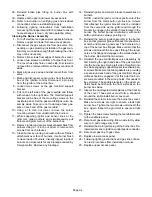
FIGURE 29
TWO-STAGE, VARIABLE SPEED INTEGRATED CONTROL BOARD
THERMOSTAT CONNECTIONS (TB1)
1/4" QUICK CONNECT TERMINALS
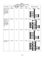
DIP SWITCH FUNCTIONS
DIP SWITCH(ES)
FUNCTION
1 and 2
Blower Off Delay
3
Second Stage ON Delay (Single-stage t'stat)
4
Not used
5 and 6
Cooling Mode Blower Speed
7 and 8
Blower Speed Adjustment
9 and 10
Cooling Mode Blower Ramping Profile
11 and 12
Heating Mode Blower Speed
DIP
SWITCHES
1 - 3
DIP
SWITCHES
5 - 12
DIAGNOSTIC
LEDs
ON-BOARD
JUMPER W951
(cut when heat pump is
used with FM21)
ON-BOARD
JUMPER W914
(cut when CCB1 or
Harmony II are used)
LEDs
LED
FACTORY-
INSTALLED
JUMPER
E20
THERMOSTAT
SELECTION
JUMPER
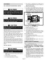
G32V units are equipped with a two-stage, variable
speed SureLight integrated control. This control manĆ
ages ignition timing, heating mode fan off delays and inĆ
door blower speeds based on selections made using the
control dip switches and jumpers. The control includes an
internal watchguard feature which automatically resets
the ignition control when it has been locked out because
the burner has failed to light. After one hour of continuous
thermostat demand for heat, the watchguard will break
and remake thermostat demand to the furnace and autoĆ
matically reset the control to relight the furnace.
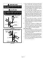
Thermostat Selection Jumper (E20)
This unit may be used with either a single-stage or two-
stage thermostat. The thermostat selection jumper, loĆ
cated just below dip switches 1 through 3, must be propĆ
erly positioned for the particular application. The jumper
is factory positioned for use with a two-stage thermostat.
If a single-stage thermostat is to be used, the jumper must
be repositioned.
a -
Select
TWO" for two-stage heating operation conĆ
trolled by a two-stage heating thermostat (factory
setting);
b -
Select SINGLE
" for two-stage heating operation
controlled by a single-stage heating thermostat.
This setting provides a timed delay before second-
stage heat is initiated.
Dip Switch Settings
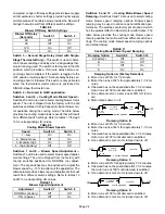
Switches 1 and 2 -- Blower Off Delay --
The blower-on
delay of 45 seconds is not adjustable. The blower-off deĆ
lay (time that the blower operates after the heating deĆ
mand has been satisfied) can be adjusted by moving
switches 1 and 2 on the integrated control board. The unit
is shipped from the factory with a blower-off delay of 90
seconds. The blower off delay affects comfort and is adĆ
justable to satisfy individual applications. Adjust the blowĆ
er off delay to achieve a supply air temperature between
90° and 110°F at the exact moment that the blower is de-