background image

Page 16

II−PLACEMENT AND INSTALLATION

Make sure unit is installed in accordance with installation in
structions and applicable codes.

A−Piping

The piping system and it’s components (oil filter, safety valves,
shutoff valves, etc.) must be designed to provide clean, air
free fuel to the burner.

An oil filter is required for all models.


Use an oil filter of gener

ous capacity for all installations. Install filter inside the building
between the tank shut−off valve and the burner. Locate filter
close to burner for easy servicing. The GAR−Ber 11BV−R or
equivalent filter (with the below specifications) is recom
mended.

Maximum Firing Rate: 10GPH (38LPH)

Micron Removal: 10

Filtering Area: 500 in.

2

 (3225.8 cm

2

)

Working Pressure: 15 PSI (103.4 kPa)

Inlet/Outlet Dimension: 3/8" (9.5 mm) NPT

Flow Rate: 45GPH (171LPH)

Care must be taken to ensure the restriction of the piping sys
tem, plus any lift involved, does not exceed the capabili
ty of the oil pump. Each installation will be different. Use
the following guide lines when determining to use a single or
two stage pump.

When using a single pipe system with the fuel supply level
with or above the burner (see figure 15) and a vacuum of 6"
(152 mm) Hg or below, a single stage fuel unit with a supply
line and no return line should be adequate. Manual bleeding of
the fuel unit is required on initial start up. Failure to bleed air
from the pump could result in an air lock/oil starvation condi
tion.

NOTE−As an extra precaution, cycle heating on and off
ten times after bleeding air from the pump. This will elim
inate air in the gun assembly.

When using a two pipe system with the fuel supply level
below the level of the burner (see figure 16) a single
stage fuel unit should be used in lift conditions of up to
10 feet (3 m) and/or a vacuum of 10" (254 mm) Hg or be
low. A two stage fuel unit should be used when lift ex
ceeds 10 feet (3 m) and/or a vacuum of 10" (254 mm) Hg
to 15" (381 mm) Hg. Both conditions require the use of a re
turn line that purges the fuel unit of air by returning it to the fuel
tank. Use table 8 when determining the run and lift for piping.

Before converting a onepipe system to a twopipe sys
tem the pump must be converted to a twopipe system.
To convert the pump, install the bypass plug according
to the instructions. Notice in the twopipe system the re
turn line must terminate 3" (76 mm) to 4" (102 mm)
above the supply inlet. Failure to do this may introduce
air into the system and could result in loss of prime.

NOTE−If using an outside tank in cold climates a number one
fuel or an oil treatment is strongly recommended.
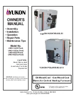
FIGURE 15

OIL PIPING

ÎÎÎÎÎÎÎÎÎÎÎÎ

ÎÎÎÎÎÎÎÎÎÎÎÎ

ÎÎÎÎÎÎÎÎÎÎÎÎ

ÎÎÎÎÎÎÎÎÎÎÎÎ

ÎÎÎÎÎÎÎÎÎÎÎÎ

ÎÎÎÎÎÎÎÎÎÎÎÎ

ÎÎÎÎÎÎÎÎÎÎÎÎ

ÎÎÎÎÎÎÎÎÎÎÎÎ

ÎÎÎÎÎÎÎÎÎÎÎÎ

ÎÎÎÎÎÎÎÎÎÎÎÎ

Air Vent

Fill

Pipe

Oil

Tank

Fuel

Unit

Aux

Filter

Shut−off

Valve

8 ft (2.4 m) 

Maximum

One Pipe Lift

ONEPIPE SYSTEM

FIGURE 16

OIL PIPING

ÎÎÎÎÎÎÎÎÎÎÎÎÎÎ

ÎÎÎÎÎÎÎÎÎÎÎÎÎÎ

ÎÎÎÎÎÎÎÎÎÎÎÎÎÎ

ÎÎÎÎÎÎÎÎÎÎÎÎÎÎ

ÎÎÎÎÎÎÎÎÎÎÎÎÎÎ

Fuel

Unit

Aux

Filter

Return

Line

Fill

Pipe

Air Vent

Oil

Tank

Inlet

Return

Line

H

3"−4"

(76mm −102mm)

R

OUTSIDE TANK FUEL UNIT ABOVE BOTTOM OF TANK.

TWOPIPE SYSTEM

TABLE 8

TWO−PIPE MAXIMUM LINE LENGTH (H + R)

3450 RPM − 3 GPH (11.4 LPH)

Lift H"

Figure 15

3/8" (10 mm) OD

Tubing

1/2" (12 mm) OD

Tubing

g

Single

Stage

Two

Stage

Single

Stage

Two

Stage

0’

(0.0 m)

84’

(25.6 m)

93’

(28.3 m)

100’

(30.5 m)

100’

(30.5 m)

2’

(0.6 m)

73’

(22.3 m)

85’

(25.9 m)

100’

(30.5 m)

100’

(30.5 m)

4’

(1.2m)

63’

(19.2 m)

77’

(23.5 m)

100’

(30.5 m)

100’

(30.5 m)

6’

(1.8m)

52’

(15.8 m)

69’

(21.0 m)

100’

(30.5 m)

100’

(30.5 m)

8’

(2.4m)

42’

(12.8 m)

60’

(18.3 m)

100’

(30.5 m)

100’

(30.5 m)

10’

(3.0m)

31’

(9.4 m)

52’

(15.9 m)

100’

(30.5 m)

100’

(30.5 m)

12’

(3.7m)

21’

(6.4 m)

44’

(13.4 m)

83’

(25.3 m)

100’

(30.5 m)

14’

(4.3m)

−−−

36’

(11.0 m)

41’

(12.5 m)

100’

(30.5 m)

16’

(4.9m)

−−−

27’

(8.2 m)

−−−

100’

(30.5 m)

18’

(5.5m)

−−−

−−−

−−−

76’

(23.2 m)

Summary of Contents for Elite OF23 Lo-Boy (Front Flue)

Page 1: ...easy cleaning while the oil burner can be removed for inspection and service The mainte nance section gives a detailed description on how this is done Information contained in this manual is intended...

Page 2: ...uires return air from both sides of cabinet Nozzle must be field provided for field conversion to higher heating input SPECIFICATIONS OHR23 Model Number OHR23Q3 105 120 OHR23Q5 140 154 Input Btuh kW l...

Page 3: ...nd FTC labeling regulations Isolated combustion system rating for non weatherized furnaces Nozzle must be field provided for field conversion to higher heating input BLOWER PERFORMANCE DATA O23 O23Q2...

Page 4: ...120 530 60 150 1230 580 1160 545 1080 510 NOTE All air data is measured external to the unit with the air filter in place OF23Q5 140 154 BLOWER PERFORMANCE External Static Air Volume at Various Blower...

Page 5: ...OWER MOTOR COMBUSTION AIR INTAKE OBSERVATION PORT CLEAN OUT PORT VENT OPENING HEAT EXCHANGER CLEAN OUT PORT FIGURE 2 OHR23 GENERAL PARTS ORIENTATION LIMIT SWITCH CONTROL BOX WITH FAN CONTROL BECKETT A...

Page 6: ...NALS ACCESSORY TERMINAL THERMOSTAT TERMINAL STRIP TB1 DETACHABLE ON EARLY 1 AND 2 MODELS ONLY BLOWER TIME ADJUSTMENT JUMPER HEATING SPEED TAP TERMINAL COOLING SPEED TAP TERMINAL CONTINUOUS FAN TERMINA...

Page 7: ...set too low residual heat in heat exchanger may cause primary limit S10 or auxilary limit S21 to trip resulting in frequent cycling of blower If this occurs adjust blower to longer time setting Figur...

Page 8: ...not after a blower or cooling demand that is when indoor thermostat switch is changed from ON to AUTO and heating cooling demand is not present the blower stops immediately FIGURE 6 FAN OFF TIME ADJUS...

Page 9: ...o low residual heat in heat exchanger may cause primary limit S10 or auilary limit S21 to trip resulting in frequent cycling of blower If this occurs adjust blower to longer time setting Thermostat Co...

Page 10: ...ER NOZZLE AIR SCOOP INLET WHEEL BLOWER FLANGE GASKET DOOR GASKET REAR ACCESS COUPLING OIL PUMP PLATE ESCUTCHEON NUT SPLINED DOOR ASSY REAR ACCESS ASSY HOUSING MAIN HOLE PLUG SCREWS AIR TUBE FLANGE ASS...

Page 11: ...LINE PEDESTAL ADAPTER NOZZLE AIR SCOOP INLET WHEEL BLOWER FLANGE GASKET MOTOR 4X4 BOX IGNITOR DOOR GASKET REAR ACCESS COUPLING FUEL PUMP PLATE ESCUTCHEON NUT SPLINED DOOR ASSY REAR ACCESS ASSY HOUSING...

Page 12: ...r temperature has returned to normal Keep motor clean to prevent starting switch from sticking All AFII motors are permanently lubricated No further oiling is required 2 Combustion Air Blower Pump Fus...

Page 13: ...er and begin a 60 second recycle delay Af ter 60 seconds the control repeats the ignition process If flame is lost three consecutive times during a single ther mostat demand the control goas into rest...

Page 14: ...while the other re mains in contact with the other terminal There should be an arc from terminal to the blade up to 3 4 away If not re place the ignitor If an arc is present then place one end of the...

Page 15: ...l board via the blower motor plug P43 2 Secondary Limit Control S21 The secondary limit S21 is used on the OHR23 series unit only The N C limit is mounted on the side and toward the back of the blower...

Page 16: ...the burner see figure 16 a single stage fuel unit should be used in lift conditions of up to 10 feet 3 m and or a vacuum of 10 254 mm Hg or be low A two stage fuel unit should be used when lift ex cee...

Page 17: ...combustion from the furnace A draft of at least 04 w c 9 9 Pa is required during burner operation 1 Local building codes may have more stringent instal lation requirements and should be consulted befo...

Page 18: ...ation provided all the air that was needed and then some In today s homes built with energy conservation in mind tight construction practices make it necessary to bring in air from outside for combust...

Page 19: ...ned air can be brought in by pro viding two permanent openings between the two spaces Each opening must have a minimum free area of 1 square inch 6 4 square centimeters per 1 000 Btu 293 W per hour of...

Page 20: ...ll cause improper burner operation and may result in a fire hazard or injury CAUTION The barometric shall be in the same atmospheric pressure zone as the combustion air inlet to the furnace Deviation...

Page 21: ...vent pipe footage from the furnace to the mechanical vent system Tjernlund or Field Controls by adding the straight vent pipe length and the equivalent elbow lengths together The barometric draft cont...

Page 22: ...ead inside diameter align the center mark of the gauge with the center of the nozzle orifice as shown in figure 27 and move the gauge from side to side at sev eral points Be careful not to scratch the...

Page 23: ...hole A reading of the overfire draft should be 0 02 w c 5 0 Pa less than the reading found in the vent connector If a posi tive reading is seen at this point the secondary heat ex changer may be soot...

Page 24: ...wire to remove the burner without disconnecting wires Once re moved just turn the burner around in the vest panel area NOTE Before disassembling any part of the burner turn off power and oil supply to...

Page 25: ...nd oil line at gun assembly as shown in figure 33 2 If motor and blower wheel are to be removed away from the burner disconnect motor wiring harness from the primary control If the motor and blower wh...

Page 26: ...access door 3 Remove two screws located in the front blower rails 4 Pull blower assembly forward enough to disconnect the motor leads 5 Disconnect heating red and or Cooling black wire s from the mot...

Page 27: ...sure locking screws are secure 6 Brush out and vacuum the vent outlet area of the outer drum and replace vent pipe 7 Clean around the burner blower deck and vestibule area C Annual Burner Maintenance...

Page 28: ...VAC spark igniting the burner When 1K1 closes the solid state switch and cad cell are ener gized When the cad cell senses light the solid state switch de energizes the safety heater keeping the burner...

Page 29: ...tage passes through contactor K1 the energizing the indoor blower B3 on heating speed 6 When heat demand is satisfied W1 of the thermostat de energizes W of the ignition control Combustion air inducer...

Page 30: ...After the venter motor establishes a draft the N O fan proving switch closes completing the circuit to the burner motor 1 2 3 FIELD CONTROL HORIZONTAL VENTING SYSTEM OPERATION SEQUENCE 1 When 1K2 clo...

Page 31: ...lution Close all leaks with cement Problem Failure to extend the length of the flue partition down to the floor De tected by inspection or smoke test Solution Extend partition to floor level Problem S...

Page 32: ...ER ACROSS R W REMOVE R G JUMPER IS UNIT LIT NO CHECK 1 PRIMARY CONTROL 2 IGNITION TRANSFORMER 3 FUEL PUMP 4 ELECTRODES 5 LIMIT SWITCH ES YES IS BLOWER RUNNING ON LOW SPEED 45 SEC AFTER FURNACE LIGHTS...

Page 33: ...immediately Thermostat begins call for fan G terminal is energized Circulating fan is energized immediately at cool speed ST9103A may be factory configured to operate heat speed in this mode Thermost...

Page 34: ...wires at the primary control If the burner starts fault is in the Flame detector exposed to light Seal off false source of light the burner starts fault is in the detector circuit short circuit in th...

Page 35: ...or plugged Nozzle strainer plugged Replace nozzle with the same size spray angle and spray type Inspect the nozzle for plugged orifice or carbon build up around orifice Poor or off center spray type F...

Page 36: ...n d t l k Too much air lean short fire Reduce combustion air check combustion Poor Fire does not lock out of safety fault may be Too little air long dirty fire Increase combustion air check combustion...

Page 37: ...erly rotating wheel Restrictions in return or supply air system Correct cause of restriction Adjustable limit control set too low Reset limit to maximum stop setting Power If voltage fluctuates fault...

Page 38: ...ace nozzle Oil Pressure Inspect fire and check oil pressure Oil pressure is too low less than 100 psi Increase oil pressure top 100psi Troubelshooting O23 OHR23 OF23 5 Units Procedure Status Correctio...

Page 39: ...k line voltage at ignitor terminals If line voltage is present replace burner control Ignition is off voltage is present replace burner control 2 7 Listen for spark after burner en ergizes after 2 sec...

Reviews: