background image

Page 22

IV-HEATING SYSTEM SERVICE CHECKS 

A-CSA Certification

All units are CSA design certified without modifications.
Refer to the EL280DFE Installation Instruction.

B-Gas Piping

CAUTION

If a flexible gas connector is required or allowed by
the authority that has jurisdiction, black iron pipe
shall be installed at the gas valve and extend outside
the furnace cabinet. The flexible connector can then
be added between the black iron pipe and the gas
supply line.

WARNING

Do not over torque (800 in-lbs) or under torque (350
in-lbs) when attaching the gas piping to the gas
valve.

Gas supply piping should not allow more than 0.5”W.C. drop
in pressure between gas meter and unit. Supply gas pipe
must not be smaller than unit gas connection.

Compounds used on gas piping threaded joints should be
resistant to action of liquefied petroleum gases.

C-Testing Gas Piping

IMPORTANT

In case emergency shutdown is required, turn off
the main shut‐off valve and disconnect the main
power to unit.  These controls should be properly
labeled by the installer.

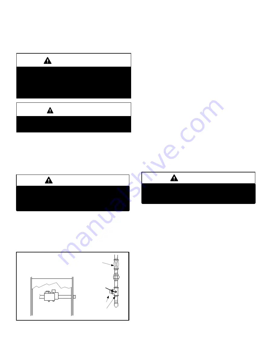
When pressure testing gas lines, the gas valve must be dis­
connected and isolated. Gas valves can be damaged if
subjected to more than 0.5 psig (14” W.C.). See figure 18

If

the pressure is equal to or less than 0.5psig (14”W.C.), use
the manual shut-off valve before pressure testing to isolate
furnace from gas supply.

FIGURE 18

MANUAL MAIN SHUT-OFF VALVE

WILL NOT HOLD TEST PRESSURE

IN EXCESS OF 0.5 PSIG (14”W.C.)

GAS VALVE

CAP

GAS PIPING TEST PROCEDURE

FIELD PROVIDED

LINE PRESSURE TAP

1/8 NPT PLUG

When checking piping connections for gas leaks, use pre­

ferred means. Kitchen detergents can cause harmful corro­

sion on various metals used in gas piping. Use of a specialty

Gas Leak Detector is strongly recommended. It is available

through Lennox under part number 31B2001. See Corp.

8411-L10, for further details.

Do not use matches, candles, flame or any other source of

ignition to check for gas leaks.

D-Testing Gas Supply Pressure

An inlet post located on the gas valve provides access to
the supply pressure. See figure 17. Back out the 3/32 hex
screw one turn, connect a piece of 5/16 tubing and connect
to a manometer to measure supply pressure. See table 14
for supply line pressure.

E-Check Manifold Pressure

After line pressure has been checked and adjusted, check

manifold pressure. Move pressure gauge to outlet pres­

sure tap located on unit gas valve (GV1). Checks of man­

ifold pressure are made as verification of proper regulator ad­

justment. Manifold pressure can be measured at any time the

gas valve is open and is supplying gas to the unit. See table

14 for normal operating manifold pressure.

IMPORTANT

For safety, connect a shut‐off valve between the
manometer and the gas tap to permit shut off of
gas pressure to the manometer.

The gas valve is factory set and should not require adjust­

ment. All gas valves are factory regulated.

Manifold Adjustment Procedure:

 1 - Connect test gauge to manifold pressure tap (figure

17) on gas valve.

 2 - Ignite unit on 

low fire

 and let run for 5 minutes to allow

for steady state conditions.

 3 - After allowing unit to stabilize for 5 minutes, record

manifold pressure and compare to value given in table
14.

 4 - If necessary, make adjustments. Figure 17 shows

location of high fire and low fire adjustment screw.

 5 - Repeat steps 2, 3 and 4 on high fire.

 6 - Shut unit off and remove manometer as soon as an ac­

curate reading has been obtained. Take care to re­
place pressure tap plug

.

 7 - Start unit and perform leak check. Seal leaks if found.

Summary of Contents for EL280DFE Series

Page 1: ...xcept where noted are recommendations only and do not consti tute code TABLE OF CONTENTS Specifications Page 2 Blower Performance Data Page 3 Parts Identification Page 4 I Unit Components Page 5 II In...

Page 2: ...g 2 3 5 3 4 Air Volume Range cfm 400 1475 780 1700 Electrical Data Voltage 120 volts 60 hertz 1 phase Blower motor full load amps 6 1 8 2 Maximum overcurrent protection 15 15 Shipping Data lbs 1 packa...

Page 3: ...02 0 70 1405 482 1235 365 1075 295 990 259 840 209 0 80 1160 369 1025 308 925 268 780 217 EL280DF070E36A PERFORMANCE Less Filter External Static Pressure in w g Air Volume Watts at Various Blower Spee...

Page 4: ...ION Control Box includes integrated control transformer and door switch Secondary Limit Internal Flue Pipe Assembly Gas Valve Burner Box Assembly Combustion Air Inducer Indoor Blower Heat Exchanger Pr...

Page 5: ...nits are equipped with the SureLight two stage inte grated control The system consists of a ignition blower control figures 4 and 5 with control pin designations in tables 1 and 2 and ignitor The cont...

Page 6: ...he DIP switch to ON for use with a single stage thermostat While in the single stage thermostat mode the burners will always fire on first stage heat The combustion air inducer will operate on low spe...

Page 7: ...T STAGE COOL SIGNAL Y2 THERMOSTAT 2ND STAGE COOL SIGNAL O THERMOSTAT SIGNAL TO HEAT PUMP REVERSING VALVE L NOT USED DH NOT USED HUM UNPOWERED NORMALLY OPEN DRY CONTACTS LI 120 VAC INPUT TO CONTROL ACC...

Page 8: ...ELECTION 1 2 3 4 5 6 ON SureLight W1W2 G Y2 Y1 C C DH L O DS R W1 W2 G Y2 Y1 C C R L DH 7 PROTECTIVE PLASTIC FILM ON DIP SWITCHES MAY BE REMOVED FOR EASE IN SETTING OF DIP SW CUT ON BOARD LINK SOLDER...

Page 9: ...rob bing equipment connected to system May require installation of larger VA transformer to be installed in furnace air handler Clears after fault recovered E 117 Poor ground detected Warning only Pr...

Page 10: ...operation after fault is cleared E 225 High pressure switch failed open Check pressure inches w c of high pressure switch closing on heat call Measure operating pres sure inches w c Inspect vent and...

Page 11: ...ating pressure inches w c Inspect vent and combustion air inducer for correct opera tion and restriction Clears when heat call finishes successfully E 273 Soft lockout Exceeded maximum number of recyc...

Page 12: ...nit is shipped from the factory with a blower off delay of 90 se conds The blower off delay affects comfort and is adjust able to satisfy individual applications Adjust the blower off delay to achieve...

Page 13: ...o provide constant torque at each of the five selectable speed taps Each tap requires 24 volts to en ergize Input Voltage Requirements The circuit is designed to be operated with AC voltage To enable...

Page 14: ...fan 1 2 3 4 or 5 on input plug P49 If 24 volts is not present problem may be up stream of plug P49 Proceed to test 4 Multi Meter set to VAC 12 0 12 0 24 Multi Meter set to VAC Check for 24 volts acros...

Page 15: ...read approxim ately the same resistance within an ohm 3 Check to see if the blower wheel spins freely FIGURE 11 Motor Test TABLE 8 Scale Measurement range in words ohms 2 M two megohm two million ohms...

Page 16: ...s are located on the valve A regu lator adjustment screw is located on the valve LPG change over kits are available from Lennox Kits include burner orifices 4 Flame Rollout Switches S47 The EL280DFE i...

Page 17: ...Page 17 EL280DFE HEATING COMPONENTS FIGURE 13 Ignitor Burners Sensor Gas Valve Manifold and Gas Orifices Rollout Switch...

Page 18: ...AC volts Test 2 Check ignitor for correct resistance Seperate the 2 pin jack plug near the manifold and check resistance of ignitor at the plug Reading should be between 39 and 70 ohms If the reading...

Page 19: ...thermostat contacts to cycle system 7 When main burners are in operation for two minutes take reading TABLE 9 Flame Signal in Microamps Normal Low Drop Out 2 6 or greater 2 5 or less 06 FIGURE 15 Meas...

Page 20: ...d stage the switch senses that the combustion air inducer is operating It closes a cir cuit to the furnace control when pressure inside the com bustion air inducer decreases to a certain set point Set...

Page 21: ...ails to operate check the following 1 Is the thermostat calling for heat 2 Are access panels securely in place 3 Is the main disconnect switch closed 4 Is there a blown fuse or tripped circuit breaker...

Page 22: ...n on various metals used in gas piping Use of a specialty Gas Leak Detector is strongly recommended It is available through Lennox under part number 31B2001 See Corp 8411 L10 for further details Do no...

Page 23: ...nd pressure switch may require adjustment or replacement to ensure proper operation at higher altitudes See table 14 for manifold pressures and table 15 for pressure switch kits and gas conversion kit...

Page 24: ...E 19 Return Supply Temperatures TEMPERATURE RISE Supply Duct Temperature Return Duct Temperature _ Temperature Rise C External Static Pressure 1 Tap locations shown in figure 20 2 Punch a 1 4 diameter...

Page 25: ...and unobstructed to provide combustion air 10 Inspect the furnace venting system to make sure it is in place structurally sound and without holes corrosion or blockage Vent system must be free and cl...

Page 26: ...e careful with the collector box gas ket If the gasket is damaged it must be replaced to prevent leakage 6 Disconnect gas supply piping Remove the screw se curing the burner box cover and remove cover...

Page 27: ...bustion air inducer Failure to replace all screws may cause leaks Inspect gaskets for any damage and replace if necessary 15 Reinstall burner box manifold assembly and burner box cover 16 Reconnect al...

Page 28: ...Page 28 VII Wiring and Sequence of Operation EL280DFE Schematic Wiring Diagram...

Page 29: ...zed on low fire first stage and ignition oc curs At the same time the control module sends a sig nal to begin an indoor blower 30 second ON delay When the delay ends the indoor blower motor is ener gi...

Page 30: ...er gized on the low fire heating speed and the HUM con tacts are energized The integrated control also initi ates a second stage on delay factory set at 7 min utes adjustable to 12 minutes 5 If the he...

Page 31: ...T ANY ON BOARD LINKS S1 T STAT FURNACE TERM STRIP OUTDOOR UNIT Not required on all units 1 Heat 2 Cool NOTE Use DIP switch 2 to set second stage heat ON delay OFF 7 minutes ON 12 minutes ON CUT ON BOA...

Page 32: ...E TERM STRIP OUTDOOR UNIT Not required on all units 2 Heat 2 Cool with t stat with humidity control OFF CUT ON BOARD LINK W915 2 STAGE COMPR CUT ON BOARD LINK W914 DEHUM S1 T STAT FURNACE TERM STRIP O...

Page 33: ...ON BOARD LINK W951 HEAT PUMP DEHUM L7724U T STAT FURNACE TERM STRIP HEAT PUMP 67M41 Y H L Y2 D B L Y2 Dual Fuel Two Stage Heat Pump ComfortSense 7000 L7724U thermostat w dual fuel capa bilities Capabl...

Page 34: ...AT PUMP CUT ON BOARD LINK W914 DEHUM L7742U T STAT FURNACE TERM STRIP HEAT PUMP 67M41 Y H L Y2 D B L Y2 Dual Fuel Two Stage Heat Pump ComfortSense 7000 L7742U thermostat w dual fuel capa bilities Capa...

Page 35: ...OR T STAT IS CYCLED OFF ON FOR 3 SEC MINIMUM NO YES FIRST LOW STAGE PRESSURE SWITCH CONTACTS OPEN NO GAS VALVE OFF COMBUSTION AIR INDUCER OFF INDOOR BLOWER OFF CONTROL REMAINS UNTIL PRESSURE SWITCH I...

Page 36: ...NDS AFTER GAS VALVE OPENS u0 19 microamps GAS VALVE OFF COMBUSTION AIR INDUCER ON INDOOR BLOWER OFF STATUS LED HEARTBEAT HAS CONTROL FAILED TO SENSE FLAME FOR FIVE CONSECUTIVE TRIES DURING A SINGLE HE...

Page 37: ...ST STAGE HEAT DEMAND SATISFIED GAS VALVE OFF COMBUSTION AIR INDUCER OFF FOLLOWING POST PURGE INDOOR BLOWER OFF WITH DELAY STATUS LED PULSE YES SECOND STAGE HEAT DEMAND SECOND STAGE HEAT DEMAND REQUIRE...

Page 38: ...ODE DIP SWITCH SET AT SINGLE YES YES FIRST AND SECOND STAGE HEAT DEMAND SATISFIED SIMULTANEOUSLY STATUS LED HEARTBEAT YES GAS VALVE OFF COMBUSTION AIR INDUCER OFF AFTER 5 SECOND LOW SPEED POST PURGE P...

Page 39: ...ZED NO IS THERE PROPER GROUND YES NO INDOOR BLOWER ENERGIZED ON FIRST STAGE COOL SPEED AFTER 2 SECOND DELAY FIRST STAGE DEMAND FOR COOL SATISFIED NO THERMOSTAT CALLS FOR SECOND STAGE COOL COMPRESSOR A...

Page 40: ...TO LOW HEAT SPEED FIRST STAGE HEAT DEMAND SATISFIED YES NO THERMOSTAT CALLS FOR SECOND STAGE HEAT YES INDOOR BLOWER SWITCHES TO HIGH HEAT SPEED AFTER 30 SECOND RECOGNITION PERIOD SECOND STAGE HEAT DE...

Reviews: