background image

www.lennoxemea.com

e-MovAir-IOM-20.04-EN

26

e-MovAir-IOM-20.04-EN

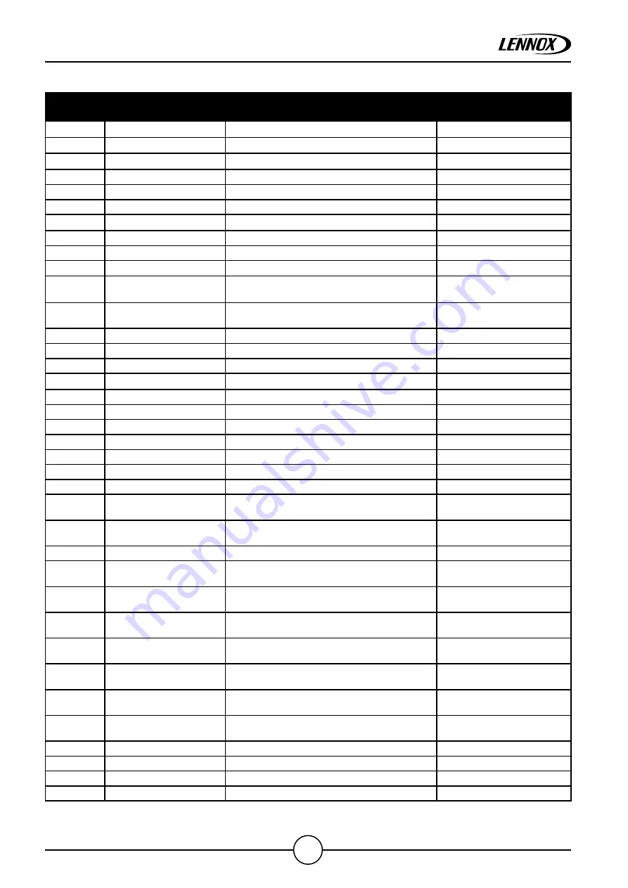
13.0. LIST AND DESCRIPTION OF ALARMS ON DISPLAY

ALARM 
NUMBER

ALARMS

ALARMS DESCRIPTION

REARM

1

Clock Alarm

Clock PCO Alarm

2

Memory Alarm

Internal memory Alarm

3

Alarm U1

Probe broken or disconnected

4

Alarm U2

Probe broken or disconnected

5

Alarm U3

Probe broken or disconnected

6

Alarm U4

Probe broken or disconnected

7

Alarm U5

Probe broken or disconnected

8

Alarm U6

Probe broken or disconnected

9

Alarm U7

Probe broken or disconnected

10

Alarm U8

Probe broken or disconnected

11

Safety Damper Open

Safety damper not opened after movement 
time

Manual

12

Smoke-fire Alarm

Doors, fire, smoke sensor alarm

Manual strong (5 seconds 
alarm button pressed)

13

Dirty filter warning

Filter warning

Auto

14

Dirty filter Alarm

Filter alarm

Auto

15

Fans thermal prot.

Fans thermal protection

Auto

16

Alarm U9

Probe broken or disconnected

17

Alarm U10

Probe broken or disconnected

18

Alarm U11

Probe broken or disconnected

19

Alarm U12

Probe broken or disconnected

20

21

Compr. 1 thermal prot.

Compressor 1 thermal protection

22

Low  press. switch c1

Low pressure switch circuit 1

Auto

23

High press. switch c1

High pressure switch circuit 1

Auto

24

Too many low sw c1 

Too many low pressure switch alarm in 
monitor time

Manual strong

25

Too many high sw c1 

Too many high pressure switch alarm in 
monitor time

Manual strong

26

Out of Enevelope c1

Compressor work out of envelope

Auto

27

Too many out Envel. c1

Too many out of enevelope alarm in monitor 
time

Manual strong

28

High press. elec. c1

Condensation pressure over threshold  circuit 
1

Auto

29

Too many high elec. c1

Too many condensation pressure over 
threshold in monitor time

Manual strong

30

out of limit time c1

Compressor is working out of limit for long 
time

Auto

31

Too many out limit c1 

Too many compressor out of limit in monitor 
time

Manual strong

32

Low press. elec. c1

Evaporation pressure under threshold  circuit 
1

Auto

33

Too many low elec. c1

Too many evaporation pressure under 
threshold in monitor time

Manual strong

34

35

36

37

IN

 DEVEL

OPMENT

/PRELIMINAR

Summary of Contents for e-MovAir Series

Page 1: ...e MovAir Packaged air handling unit Installation Operating Manual e MovAir IOM 20 04 EN ...

Page 2: ...ECKS BEFORE SHIPMENT 2 0 TRANSPORT 3 0 UNLOADING 3 1 CHECKS UPON RECEIPT 3 2 HOISTING AND HANDLING 3 3 STORAGE 4 0 UNIT IDENTIFICATION 5 0 INSTALLATION AND COMMISSIONING 5 1 DEFINITIONS 5 2 SAFETY STANDARDS 5 3 SELECTING THE SITE OF INSTALLATION 5 4 JOINING THE SECTIONS 5 5 CONNECTIONS TO THE DUCTS 5 6 WATER CONNECTIONS 5 6 1 COIL WATER CONNECTIONS 5 6 2 DISCHARGE CONNECTIONS 5 7 ELECTRICAL CONNEC...

Page 3: ... order to implement all necessary measures to eliminate the risk or limit its effects if it cannot be deleted Each stakeholder should warn their client of residual risks You must read and be familiar with this operating manual prior to commission the unit Please closely follow the instructions We would like to stress the importance of training with respect to the correct handling of the unit Pleas...

Page 4: ...radiated emission and immunity these differences do not alter the results F GAS REGULATION PLEASE READ THE SAFETY DATA SHEET OF THE REFRIGERANT BEFORE ANY INTERVENTION OR INSTALLATION OF THE MACHINE Operators of refrigeration equipment s must comply with the obligations defined in Regulation on Fluorinated greenhouse gases F Gas Regulation on substances that deplete the ozone layer Non compliance ...

Page 5: ...riptions provided by us remain the property of Lennox and must not be used except in operation of this product reproduced issued to or made available to third parts without the prior written agreement of Lennox The technical information and specifications contained in this manual are for reference only The manufacturer reserves the right to modify these without warning and without obligation to mo...

Page 6: ...it check the pressure with manometers or pressure sensors and purge the circuit Never leave a unit stopped with valves closed on the liquid line refrigerant could be trapped and the pressure would rise All installation parts must be maintained by the personnel in charge in order to avoid material deterioration and injuries to people Faults and leaks must be repaired immediately The authorized tech...

Page 7: ...filters Don t walk Don t strap Warning main switch supplied from bottom Gravity center OK to send document Protection by water filter mandatory Protection by strainer filter mandatory Transport of non flammable liquefied gas Transport of flammable liquefied gas Information to read CMIM marking Morocco Electrical connections can loosen during transport Please check them before start up CE marking C...

Page 8: ...ex 1 1 5 1 EN 60204 1 2014 30 EU EMC Directive Pressure Equipment Directive 2014 68 EU EU 517 2014 F Gas 2009 125 EC Ecodesign EU 2016 2281 Rooftop Gas Equipment Regulation EU 2016 426 2015 863 EU RoHS directive 2012 19 EU WEEE EC 1005 2009 1907 2006 UE REACH LABELS The rooftop may be marked with the following warning labels to alert to potential hazards on or near the potentially hazardous part T...

Page 9: ...t number of supports for the piping according to their size and weight under operating conditions and to design the piping to avoid a water hammer phenomenon For technical reasons it is not possible to carry out hydrostatic tests on all our units so leak tests are carried out as a compensatory measure The entire circuit is checked using leak detectors For machines charged with refrigerant at the e...

Page 10: ...ff by employees having valid electrical qualification and authorization WORK ON THE REFRIGERATING CIRCUIT S Monitoring of the pressures draining and filling of the system under pressure shall be carried out using connections provided for this purpose and suitable equipment To prevent the risk of explosion due to spraying of coolant and oil the relevant circuit shall be drained and at zero pressure...

Page 11: ...nd in particular for return and curbs It s also valid to reach other parts of the unit filters refrigerant circuit etc It s advised to fix curbs and roofcurbs to the unit Installation of the unit and accessibility must be compliant with the local regulations Ensure that all access equipment allow maintenance operation in safety electrical cabinet main switch panels filter refrigerant circuit It is...

Page 12: ...tings of the unit WARNING The units are not designed to resist to a fire The installation site must comply with the standards relating to fire protection In case of installation of the units in an area recognized as being potentially at risk for natural phenomena tornado earthquake tidal wave lightning please follow the standards and regulations and provide the necessary devices to prevent from th...

Page 13: ...alue likely to be achieved for the specified operational voltage The customer must have a suitable electrical supply It is therefore important to check whether the supply voltage stated on the unit s rating plate is compatible with that of the mains electrical supply The rating plate also states year of manufacture weight of the unit type of refrigerant used GWP Global warming potential required c...

Page 14: ...ns lifting eyebolts Upon customer request a special certificate can be issued relating to the above checks 2 0 TRANSPORT All the units are supplied without packaging Only upon request following quotation packaging is provided in cages normal or special water resistant crates etc The components that due to technical constructional transport or other requirements are not fitted on the unit but sent ...

Page 15: ...ADEQUATE LENGTH TO PREVENT THE CABLES FROM DAMAGING THE CASING WHEN TIGHTENED Place the goods down with care avoiding sudden movements or worse dropping the goods Where the support feet are fitted sizes eM03AH025 eM04AH028 eM05AH030 only the units can be handled by fork lift Caution Widen the forks as much as possible so as to balance the load Dip the ends of the forks to avoid damaging the bottom...

Page 16: ...LL LIABILITY FOR THE FAILURE TO OBSERVE THE FOLLOWING SAFETY STANDARDS IT FURTHERMORE DECLINES ALL LIABILITY FOR DAMAGE CAUSED BY THE IMPROPER USE OF THE UNIT AND OR MODIFICATIONS MADE WITHOUT AUTHORISATION INSTALLATION MUST BE PERFORMED BY SPECIALIST PERSONNEL During installation always wear suitable safety clothing for example glasses gloves etc as described in the EC 686 89 and following standa...

Page 17: ...as coils filters etc If the unit is hung from the ceiling given the weights involved all the sections that make up the air handling unit must be connected to the ceiling As the motor fan assembly and the moving parts feature vibration dampers and are dynamically insulated from the structure by the vibration dampers on the base and the flexible joint on the outlet external vibration dampers are not...

Page 18: ...TTOM AND THE OUTLET AT THE TOP FOR THIS REASON APPROVAL IS ALWAYS REQUIRED OF THE CONSTRUCTIONAL DRAWINGS THAT HIGHLIGHT THE SIDE OF THE FITTINGS MOREOVER THE UNITS ARE FITTED WITH SPECIAL PLATES THAT INDICATE THE WATER INLET AND OUTLET The direct expansion coils have welded fittings The connections should be tightened with care taken to avoid damage The path of the pipes must be designed so as no...

Page 19: ...ust be performed by specialist personnel Check that the voltage and frequency shown on the unit s rating plate match the mains power supply CONNECT THE UNIT AND ALL ITS ACCESSORIES USING LES WITH A SUITABLE CROSS SECTION FOR THE POWER RATINGS AND IN COMPLIANCE WITH THE LOCAL STANDARDS IN FORCE THE SIZE OF THE CABLES MUST IN ANY CASE GUARANTEE A VOLTAGE DROP WHEN STARTING OF LESS THAN 3 OF THE RATE...

Page 20: ...TH THE DOORS CLOSED THE DOORS SHOULD ONLY BE OPENED WHEN THE UNIT IS OFF Generals Rotate by hand all the axles of the fans to make sure they freely rotate Clean the fans and all internal components of the unit from dirt in case they remained for long time exposed to external agents Check the blades of the fans they don t have to be damaged during transport operations Check the seal of the panels a...

Page 21: ...umber and the frequency of the operations to be completed for the correct maintenance of the air handling unit depends mainly on the quality of the fluids treated that is air and water The air may be particularly damaging if it contains significant amounts of pollutants or aggressive substances Industrial exhausts Salinity Chemical fumes Heavy dust These substances on coming into contact with the ...

Page 22: ...or especially dirty air REGENERABLE PLEATED SYNTHETIC PRE FILTERS G3 G4 Cleaning is performed by simply shaking with compressed air or a vacuum cleaner by washing with a jet of water Replacement is left to the judgement of the maintenance personnel however it is recommended when the filter after cleaning remains dark in colour and the layer is no longer transparent when held up to the light Monthl...

Page 23: ...efrigerant gas controlling the evaporative pressures and the condensation pressures of the circuit in summer and winter mode heat pump Check the proper operations of the carter resistances for each compressor Check the proper operations of the pressure switch for the high pressure and the low pressure Take care of the filters cleaning if any and of the condensation coils List of the suggested main...

Page 24: ...e scroll Change the electrical connections to the motor Noise Excessive flow rate Flow rate Reduce the flow rate Fan unbalanced Vibrations on the base Replace the fan Howling of the magnetic motor Mains voltage Restore correct mains voltage Foreign material in the scroll Fan Remove foreign bodies and check for damage Entrainment of water Excessive flow rate Flow rate Reduce the flow rate Drain tra...

Page 25: ...ries air handling units are manufactured in compliance with the safety standards envisaged by the European Union Machine Directive All of the e MovAir series air handling units are applied with a danger sign to warn of the presence of moving parts IT IS RECOMMENDED EVEN IF THIS IS NOT THE MANUFACTURER S RESPONSIBILITY To fit the air handling unit with an isolating switch especially if the electric...

Page 26: ...1 Probe broken or disconnected 19 Alarm U12 Probe broken or disconnected 20 21 Compr 1 thermal prot Compressor 1 thermal protection 22 Low press switch c1 Low pressure switch circuit 1 Auto 23 High press switch c1 High pressure switch circuit 1 Auto 24 Too many low sw c1 Too many low pressure switch alarm in monitor time Manual strong 25 Too many high sw c1 Too many high pressure switch alarm in m...

Page 27: ...c c2 Condensation pressure over threshold circuit 2 Auto 49 Too many high elec c2 Too many condensation pressure over threshold in monitor time Manual strong 50 out of limit time c2 Compressor is working out of limit for long time Auto 51 Too many out limit c2 Too many compressor out of limit in monitor time Manual strong 52 Low press elec c2 Evaporation pressure under threshold circuit 2 Auto 53 ...

Page 28: ...ase read this manual carefully and keep it for future reference Due to LENNOX EMEA ongoing commitment to quality the specifications ratings and dimensions are subject to change without notice and without incurring liability Improper installation adjustment alteration service or maintenance can cause property damage or personal injury Installation and service must be performed by a qualified instal...

Reviews: