22
OPERATING THE BOILER
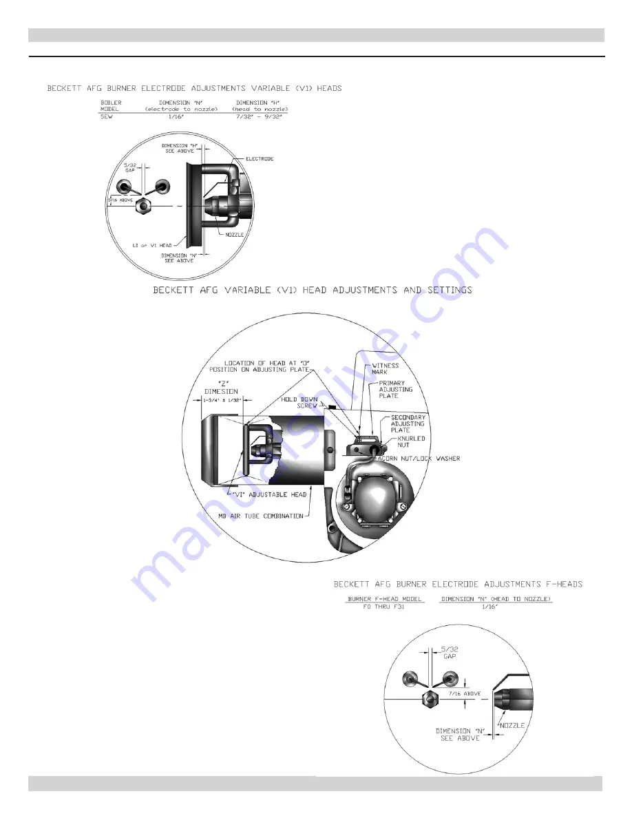
Figure 13 -Burner Adjustments and Settings
Page 1: ...alteration service or maintenance could result in death or serious injury Refer to this manual for assistance For additional information consult a qualified installer service agency or the oil suppli...
Page 2: ...or moderate injury WARNING Indicates a hazardous situation which if not avoided could result in death or serious injury DANGER Indicates a hazardous situation which if not avoided WILL result in death...
Page 3: ...3 5 8 X 8 X 15 21 6 11 Mbh 1 000 BTU per hour BTU British Thermal Unit Heating Capacity based on 13 CO2 with a 0 02 w c draft over fire and a 1 smoke or less Testing was done in accordance with the D...
Page 4: ...will automatically lift open Lifting of the safety relief valve can discharge large quantities of steam and hot water which may damage the surroundings Before installing the safety relief valve read t...
Page 5: ...assage is required for access to another side for cleaning servicing inspection or replacement of any parts that may normally require attention Install boilers at least 6 from combustible material on...
Page 6: ...IRCULATING PUMP IN RETURN LINE OR AFTER THE EXPANSION TANK SHUT OFF VALVE OIL FILTER OIL LINES FOUNDATIONS TO OUTSIDE LINES TO OTHER APPLIANCES SERVICE LINE OVERCURRENT PROTECTED SAFETY SWITCH 2 FILL...
Page 7: ...input of all combustion equipment installed in combined space shall be considered in mak ing this determination Each opening shall have minimum free area of one square inch per 1 000 Btu per hour of...
Page 8: ...the enclosure 3 When communicating with outdoors through hori zontal ducts each opening shall have minimum free area of one square inch per 2 000 Btu per hour of total input rating of all equipment in...
Page 9: ...discharge piping to avoid reducing safety relief valve relieving capacity below minimum relief valve capacity stated on rating plate Run pipe as short and straight as possible to location protecting...
Page 10: ...SYSTEMS LARGE WATER CONTENT SYSTEMS PIPING ARRANGED FOR POWER PURGING AIR OUT OF THE SYSTEM PIPING REFER TO THIS MANUAL S SECTION ON FILLING THE SYSTEM WITH WATER OPTION 1 SYSTEM PIPING Figure 7 Bypas...
Page 11: ...YFROM EXPANSION TANK NOTE CIRCULATORCANALSOBEINSTALLEDON RETURN PIPING PIPING ARRANGED FOR POWER PURGING AIR OUTOFSYSTEMPIPING REFERTOTHISMANUAL S SECTIONON FILLINGTHESYSTEMWITHWATER OPTION 1 Figure 8...
Page 12: ...PS AWAY FROM EXPANSION TANK PIPING ARRANGED FOR POWER PURGING AIR OUT OF SYSTEM PIPING REFER TO THIS MANUAL S SECTION ON FILLING THE SYS TEM WITH WATER OPTION 1 SYSTEM PIPING Figure 9 System Piping Ar...
Page 13: ...ON SUPPLY PIPING PUMPS AWAY FROM EXPANSION TANK PER THIS MANUAL USE OPTION 2 IN FILLING THE SYSTEM WITH WATER THIS PIPING ARRANGEMENT CAN BE USED WITH ZONE VALVES OR ZONE CIRCULATORS SYSTEM PIPING Fig...
Page 14: ...s are used Tankless coils are meant to provide domestic hot water for intermittent draws not continuous flow NOTICE Do not use tankless coil if your water is excessively hard with lime or other deposi...
Page 15: ...mption Tankless coil performance will fall as concentration of antifreeze is increased Refer to boiler and piping water volumes tables BOILER WATER VOLUMES Number of Boiler Section Total Volume Gallon...
Page 16: ...IMNEY SIZES FIRING RATE gph CHIMNEY HEIGHT ft NOMINAL CHIMNEY ROUND LINER INSIDE SQUARE LINER INSIDE 0 60 1 30 15 8 x 8 6 6 x 6 1 31 1 80 15 8 x 8 7 6 x 6 1 81 1 75 20 8 x 8 8 6 x 6 For elevations abo...
Page 17: ...17 TYPICAL CHIMNEY CONNECTION Figure 12 Typical Chimney Connection...
Page 18: ...volt electrical supply to L1 and L2 terminals on limit and two thermostat wires to T and T terminals on same limit See wiring diagram page 28 Run separate circuit from separate over current protection...
Page 19: ...ging drain valve runs air free close isolation valve or zone valve Re peat this procedure for remaining heating zones D Once all zones are filled with water and purged of air close power purging drain...
Page 20: ...desired over fire draft Start Fill entire system with water Vent all air from sys tem following section for Filling The Boiler Fuel Units And Oil Lines Install oil line s to oil burner Recommend using...
Page 21: ...race measure CO2 and as insurance margin increase air to sufficiently reduce CO2 by to 1 If clean fire cannot be obtained it is necessary to verify burner head and electrode alignment Proper electrode...
Page 22: ...22 OPERATING THE BOILER Figure 13 Burner Adjustments and Settings...
Page 23: ...full of vapor or when the combustion chamber is very hot Check Thermostat Operation Follow instructions included with your thermostat Locate thermostat five feet above the floor on inside wall Locate...
Page 24: ...ent that may lodge on valve seat Permit valve to snap shut Refer to valve manufacturer s instructions packaged for more details Conventional Expansion Tank Tank may become water logged or may receive...
Page 25: ...by cutting end of flue brush off and inserting it into drill When brushing take care to not damage target wall with flue brush 6 Carefully vacuum soot accumulations from combus tion chamber area take...
Page 26: ...assembly make sure head location and size if applicable are per manufacturer s recom mendations If burner being used has damaged head replace head with same head recommended for use on this boiler 6 I...
Page 27: ...tors not heating Open radiator vents to excess air Check flow control valve if used It may be in closed position Circulating pump not running Check over current protection Check relay operation Poor e...
Page 28: ...8 ELECTRICAL WIRING Figure 16 Boiler Honeywell L7248L Control When Low Limit Is Used Set ELL Parameter On L7248 Honeywell Control To On Boilers Factory Equipped With Tankless Coil Are Factory Set To O...
Page 29: ...7 Honeywell L7248L Control With Reillo F5 F10 Burner ELECTRICAL WIRING When Low Limit Is Used Set ELL Parameter On L7248 Honeywell Control To On Boilers Factory Equipped With Tankless Coil Are Factory...
Page 30: ...30 ELECTRICAL WIRING Figure 18 Honeywell L7248L Control Wiring with Zone Pumps and Argo ARM Switching Relay With Tankless coil Shown...
Page 31: ...burner fan motor to pre purge combustion chamber and oil pump to bring supply oil pressure up to its set point helping to provide clean light off LIMIT CONTROL provided Refer to manufacturer instructi...
Page 32: ...PRODUCT LITERATURE Lennox Industries Inc Dallas Texas...