Page 11
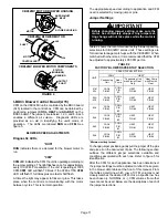
CBX32MV MOTOR BLOWER HOUSING
MOTOR
BLOWER HOUSING
FIGURE 4
CBX32MV BLOWER MOTOR
B3
MOTOR
CONTROLLER
SHAFT
J49
J48
CBX32MV BLOWER MOTOR COMPONENTS
STATOR
(WINDINGS)
OUTPUT
SHAFT
BEARING
ROTOR
ARROW MUST
BE UP
I−BDC3 Blower Control Board (A15)
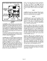
CFM on the CBX32MV unit is controlled by the BDC3 board
(A15) located in the control box. CFM can be obtained by
positioning jumpers
(COOL, HEAT
and
ADJUST)
on the
BDC3 board. The jumpers are labeled 1,2,3, and 4. Each
enables a different air volume. Diagnostic LEDs are
provided as an aid in identifying the unit’s mode of
operation. The LEDs are labeled
RUN
and
CFM
. See
BLOWER SPEED ADJUSTMENTS
Diagnostic LEDs
RUN"
RUN
indicates there is a demand for the blower motor to
run.
CFM"
CFM
LED indicates the CFM the unit is operating according to
the jumper settings. The light flashes once for approximately
every 100 CFM. For example, if the unit is operating at 1000
CFM,
CFM
LED will flash 10 times. If the CFM is 1150,
CFM
LED will flash 11 full times plus one fast or half flash.
At times the light may appear to flicker or glow. This takes
place when the control is communicating with the motor
between cycles. This is normal operation.
The appropriate speed according to application and CFM
need is selected by moving jumper pins.
Jumper Settings
IMPORTANT
Before changing jumper setting, make sure the
motor has completely stopped. Any jumper set-
ting change will not take place while the motor is
running.
Table 2 shows the recommended factory blower speed tap
selections for CBX32MV series units. These settings are
for nominal tonnage match−ups with the CBX32MV. When
matched with other sizes, it is recommended that the CFM
be adjusted to approximately 400 CFM per ton.
TABLE 2
FACTORY BLOWER SPEED TAP SELECTION
UNIT
SPEED TAP SELECTION
COOL"
HEAT"
Condensing
Unit
Heat
Pump
*Condensing Unit
with Electric Heat
Only
*Heat Pump
with Electric
Heat
−018/
024
COOL
PIN #3
COOL
PIN
#3
HEAT
PIN #4
HEAT
PIN #4
−024/
−030
COOL
PIN #3
COOL
PIN
#3
HEAT
PIN #4
HEAT
PIN #4
−036
COOL
PIN #3
COOL
PIN
#3
HEAT
PIN #4
HEAT
PIN #4
−048
COOL
PIN #2
COOL
PIN
#2
HEAT
PIN #1
HEAT
PIN #1
−060
COOL
PIN #3
COOL
PIN
#3
HEAT
PIN #1
HEAT
PIN #1
−068
COOL
PIN #3
COOL
PIN
#3
HEAT
PIN #4
HEAT
PIN #4
*Minimum setting for heat.
To change jumper positions, gently pull the jumper off the pins
and place it on the desired set of pins. The following section
outlines the different jumper selections available and
conditions associated with each one. Refer to figure 5 for
identification.
After the CFM for each application has been determined,
the jumper settings must be adjusted to reflect those given
in the blower data tables at the front of this manual. From
the tables determine which row of CFM volumes most
closely matches the desired CFM. Once a specific row has
been chosen (+, NORMAL, or −), CFM volumes from other
rows cannot be used. Below are the descriptions of each of
the jumper selections.


