background image

Page 12

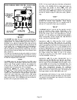
BDC3 VARIABLE SPEED CONTROL  SELECTIONS

FIGURE 5

JP1 15 PIN PLUG

(BOARD TO MOTOR)

1

2

3

4

1

2

3

4

1

2

3

4

TEST

+

NORM

ADJUST

HEAT

COOL

DELAY

CFM RUN

24V/1A

ACC

JP1

ACCESSORY RELAY

CONTACTS

(DRIVES OPTIONAL

ACCESSORY

RELAY)

OPERATIONAL

SELECTOR PINS

(Affects both heating

and cooling modes)

DIAGNOSTIC

DS LEDS

HEATING SPEED
SELECTOR PINS

COOLING SPEED

SELECTOR PINS

FAN DELAY

SELECTOR PINS

1

5

11

15

ADJUST"

The 

ADJUST

 pins allow the motor to run at normal speed,

approximately 10% higher, or approximately 10% lower than
normal speed. The blower tables give three rows (+,
NORMAL, and −) with their respective CFM volumes. Notice
that the normal adjustment setting for heat speed position #3
is 1315 CFM. The +  adjustment setting for that position is
1445 CFM and for the − adjustment setting is 1185 CFM.
After the adjustment setting has been determined, chose the
remainder speed jumper settings from those offered in the
table in that row.
The TEST pin is available to bypass the BDC3 control and
run the motor at approximately 70% to test that the motor is
operational. This is beneficial primarily in troubleshooting.
G must be energized for motor to run.

COOL"

The 

COOL

 jumper is used to determine the CFM during

either 1) cooling or 2) heat pump operation without a call for
electric heat. These jumper selections are activated for
cooling when Y2 and DS terminals in the CBX32MV are
energized and for heating when Y2 is energized.
Applications 

without

 the Lennox SignatureStat

t

 or

Efficiency

Plus

TM

 CCB1 humidity control will provide 70% of

the 

COOL 

CFM during first−stage cooling for two−speed

outdoor units. Units built prior to August 2002, will provide
either 60% (−048, −060 series units) or 65% (−036 series
units) of the 

COOL 

CFM during first stage cooling for two

stage outdoor units. 100% of 

COOL

 speed is provided for

systems with a single−speed outdoor units.

NOTE − For two speed heat pump units blower will operate at
60%, 65% or 70% of 

COOL 

CFM.

 For single speed heat pump

units blower will operate at 100%


COOL 

CFM until

supplemental electric heat is demanded. At that time, the
blower will operate at 

HEAT 

speed selected. This arrangement

provides for warmer supply air during heat pump operation
only.

HEAT"

The 

HEAT

 jumper is used to determine CFM during a W1

demand for electric heat operation. These jumper
selections are activated when W1 is energized with or
without a Y1 demand for heat pump compressor.

DELAY"

The 

DELAY

 jumper is used to set the specific motor fan

mode of operation during cooling. Depending on the
application, one of four fan options may be chosen by
moving the jumper pins to the appropriate set of pins.
Options 1, 2, 3, or 4 will have an  increased dehumidification
effect on the system.  Option 1 will have the  least effect and
option 4 will have the greatest effect.

Applications 

with 

the Efficiency

Plus

 CCB1 humidity

control create different CFM volumes. For example,
during a first−stage cooling call (two−speed outdoor unit)
with no demand from the CCB1, the air volume is 40% of
the 

COOL

 jumper selection. For a normal 

COOL

 (Pin #2

setting for CBX32MV−036), the CFM is 1125; the reduced
speed is 450 CFM (1125 x 40% = 450). This arrangement
provides for additional dehumidification during standard
first stage cooling. See tables 10 and 11 for various
scenarios concerning use of the CCB1 humidity control
and the CBX32MV series unit.

Applications 

with 

the Lennox SignatureStat but no

demand for de−humidification will operate as follows:
during a first−stage cooling call (two−stage outdoor unit),
the air volume is 70% of the 

COOL

 jumper selection. For a

normal 

COOL

 (Pin #2 setting for CBX32MV−036), the

CFM is 1125; the reduced speed is 788 CFM (1125 x 70% =
788). This arrangement provides for additional
dehumidification during standard first stage cooling. See
tables 12 and 13 for various scenarios concerning use of
the SignatureStat  and the CBX32MV series unit.

For applications with Harmony

r

 zone control, the blower

CFM volume is determined by the Harmony control center.
This speed is not adjustable. See footnotes in the blower
tables (table of contents).

Summary of Contents for CBX32MV-048

Page 1: ...clude the optional Lennox ComfortSense 7000 SignatureStatt or Efficiency Plus Comfort Management Control CCB1 The purpose of both controls is to vary indoor blower speed in response to indoor dehumidification demand When a two speed outdoor unit is used compressor speed can also be controlled by the SignatureStat or CCB1 in response to indoor dehumidification demand Information contained in this m...

Page 2: ...ons kW 1 5 2 5 3 7 2 2 5 7 8 8 3 10 6 Refrigerant R 410A R 410A R 410A Connections in mm Suction vapor line sweat 5 8 15 8 3 4 19 3 4 19 Liquid line sweat 3 8 9 5 3 8 9 5 3 8 9 5 Condensate drain fpt 2 3 4 19 2 3 4 19 2 3 4 19 Indoor Coil Net face area ft 2 m2 3 56 0 33 4 44 0 41 5 0 0 46 Tube outside diameter in mm 3 8 9 5 3 8 9 5 3 8 9 5 Number of rows 3 3 3 Fins per inch fins per m 12 472 12 47...

Page 3: ...ns per m 12 472 12 472 12 472 Blower Data Wheel nominal diameter x width in mm 12 x 9 305 x 229 12 x 9 305 x 229 15 x 9 381 x 229 Motor output hp W 1 746 1 746 1 746 Filters 1 Number and size in 1 20 x 24 x 1 1 20 x 24 x 1 1 20 x 25 x 1 mm 508 x 610 x 25 508 x 610 x 25 508 x 635 x 25 Shipping Data 1 Package lbs kg 212 96 212 96 244 111 ELECTRICAL DATA Voltage phase 60hz 208 230V 1ph 208 230V 1ph 2...

Page 4: ... 142 154 172 190 206 230 Tap 2 155 176 197 221 237 260 278 295 310 Tap 3 237 260 289 305 314 337 356 373 390 Tap 4 338 361 379 409 433 457 447 426 406 COOL Speed Tap 1 36 47 61 71 81 95 106 118 135 Tap 2 89 103 118 129 143 163 177 197 207 Tap 3 183 198 229 248 266 290 307 327 343 Tap 4 266 294 315 330 349 373 390 411 401 CBX32MV 018 024 BLOWER MOTOR WATTS AT NORM BDC3 SETTING Adjust Jumper at NORM...

Page 5: ...0 265 310 345 365 Tap 3 140 190 225 250 290 320 350 405 450 Tap 4 215 250 285 315 350 390 440 480 505 COOL Speed Tap 1 45 60 90 120 140 155 165 185 200 Tap 2 80 110 135 165 205 250 285 315 335 Tap 3 150 195 225 260 295 320 370 425 465 Tap 4 265 315 350 400 440 485 525 555 605 CBX32MV 024 030 BLOWER MOTOR WATTS AT NORM BDC3 SETTING Adjust Jumper at NORM Setting BDC3 Jumper Speed Positions Motor Wat...

Page 6: ...1 220 235 265 290 310 335 360 385 465 Tap 2 285 305 330 355 380 405 430 450 475 Tap 3 345 365 405 430 455 485 515 545 570 Tap 4 470 495 515 530 545 560 575 595 610 COOL Speed Tap 1 145 165 200 225 250 275 300 325 350 Tap 2 225 245 265 290 320 350 370 395 410 Tap 3 305 325 350 390 420 445 475 505 535 Tap 4 470 495 515 530 545 560 575 595 610 CBX32MV 036 BLOWER MOTOR WATTS AT NORM BDC3 SETTING Adjus...

Page 7: ...1 455 505 540 585 630 665 710 745 780 Tap 2 555 595 645 675 730 780 820 865 895 Tap 3 680 720 770 820 865 900 945 985 1030 Tap 4 730 780 825 870 920 970 1020 1055 1110 COOL Speed Tap 1 300 335 370 360 435 465 500 535 575 Tap 2 425 475 500 545 585 635 670 710 745 Tap 3 625 660 705 755 810 850 885 940 970 Tap 4 700 750 800 845 895 940 990 1030 1080 CBX32MV 048 AND CBX32MV 060 BLOWER MOTOR WATTS AT N...

Page 8: ...690 765 835 865 Tap 3 540 585 635 695 750 800 815 840 865 Tap 4 665 710 755 770 790 810 830 845 870 COOL Speed Tap 1 255 290 320 365 415 455 505 550 590 Tap 2 355 390 425 475 515 580 630 695 750 Tap 3 505 565 610 70 715 790 815 845 865 Tap 4 725 745 755 770 790 810 830 850 870 CBX32MV 068 BLOWER MOTOR WATTS AT NORM BDC3 SETTING Adjust Jumper at NORM Setting BDC3 Jumper Speed Positions Motor Watts ...

Page 9: ... COMPLETE WITH SCREEN BLOWER ACCESS PANEL COIL ACCESS PANEL UPFLOW DOWNFLOW DRAIN PAN FIGURE 2 CBX32MV CONTROL BOX TERMINAL STRIP TB1 R W3 W2 W1 G C TRANSFORMER T1 SMALL ELECTRIC HEAT KNOCK OUT FOR 2 5 15 kW BLOWER RELAY K20 LARGE ELECTRIC HEAT ADDITIONAL KNOCK OUT FOR 20 30 kW GROUNDING LUGS TERMINAL STRIP TB2 0 Y1 Y2 DS BDC3 BLOWER CONTROL A15 ...

Page 10: ... K20 is energized its N O contacts close to energize jack plug JP46 pin 2 located on blower drive control A15 When JP46 2 is energized the blower drive control immediately energizes the blower on heating speed Heating speed will override cooling speed K20 2 will energize the economizer if used refer to wiring diagram FIGURE 3 BLUE YELLOW ORANGE RED BLACK 240 VOLTS 208 VOLTS PRIMARY SECONDARY 208 2...

Page 11: ...e sure the motor has completely stopped Any jumper set ting change will not take place while the motor is running Table 2 shows the recommended factory blower speed tap selections for CBX32MV series units These settings are for nominal tonnage match ups with the CBX32MV When matched with other sizes it is recommended that the CFM be adjusted to approximately 400 CFM per ton TABLE 2 FACTORY BLOWER ...

Page 12: ...OL CFM For single speed heat pump units blower will operate at 100 COOL CFM until supplemental electric heat is demanded At that time the blower will operate at HEAT speed selected This arrangement provides for warmer supply air during heat pump operation only HEAT The HEAT jumper is used to determine CFM during a W1 demand for electric heat operation These jumper selections are activated when W1 ...

Page 13: ... is met motor runs at 100 for 45 seconds C Motor ramps down to stop OFF OFF A B C 100 CFM 100 CFM 45 seconds COOLING DEMAND CB32XMV units date coded prior to 2 2006 will delay 60 seconds 3 Pins Jumpered A Motor runs at 82 for approximately 7 1 2 minutes If demand has not been satisfied after 7 1 2 minutes B Motor runs at 100 until demand is satisfied C Once demand is met motor ramps down to stop O...

Page 14: ... moisture check 60 65 70 OF COOL SPEED Disconnect power to the unit Change delay pin setting on the BDC3 board to 1 Remove wires from terminal strips in control box Install jumpers between R and Y1 and R and G Turn on power to unit Blower should operate on 60 65 or 70 of cool speed When check is complete disconnect power and replace delay setting to original position Reduced blower speed for produ...

Page 15: ...ed on the electric heat vestibule panel and are energized by a 24V heating demand W1 W2 and W3 via jack plug 2 J2 which is used to connect electric heat to the blower coil control circuit When energized the internal resistance heats the bi metal disk causing the contacts to close When the relay is de energized the disk cools and the contacts open The relays energize different stages of heat as wel...

Page 16: ...CB 10L11 50A Circuit breaker ECB29EH 9CB 91K67 50A Circuit breaker 2 208 6 8 23 100 4 3 46 50 4 3 46 50 220 7 6 25 800 4 3 52 60 4 3 52 60 230 8 3 28 200 4 3 52 60 4 3 52 60 240 9 0 30 700 4 3 52 60 4 3 52 60 10 kW 6 lbs ECB29 10 28K35 Terminal Block ECB29 10CB 28K36 60A Circuit breaker 2 208 7 5 25 600 4 3 51 60 220 8 4 28 700 4 3 53 60 230 9 2 31 400 4 3 55 60 240 10 0 34 100 4 3 58 60 12 5 kW 1...

Page 17: ...1 3 38 400 4 3 28 37 30 4 50 220 12 6 43 000 4 3 31 42 35 60 230 13 8 47 000 4 3 31 42 35 60 240 15 0 51 200 4 3 31 42 35 60 20 kW 19 lbs ECB29 20CB 11L31 1 50A 1 60A Circuit breaker ECB29EH 20CB 91K70 1 50A 1 60A Circuit breaker 4 208 15 0 51 200 4 3 47 41 50 60 220 16 8 57 300 4 3 52 46 60 60 230 18 4 62 700 4 3 52 46 60 60 240 20 0 68 200 4 3 52 46 60 60 THREE PHASE ELECTRIC HEAT 8 kW 5 lbs ECB...

Page 18: ...A 1 60A Circuit breaker ECB29EH 20CB 91K70 1 50A 1 60A Circuit breaker 4 208 15 0 51 200 9 1 53 41 60 60 220 16 8 57 300 9 1 58 46 60 60 230 18 4 62 700 9 1 58 46 60 60 240 20 0 68 200 9 1 58 46 60 60 25 kW 19 lbs ECB29 25CB 28K40 3 50A Breakers 6 208 18 8 64 100 9 1 49 31 31 50 4 45 4 45 220 21 0 71 700 9 1 54 35 35 60 50 50 230 23 0 78 300 9 1 54 35 35 60 50 50 240 25 0 85 300 9 1 54 35 35 60 50...

Page 19: ... HE1 ELECTRIC HEAT VESTIBULE PANEL ELECTRIC HEAT SEQUENCER RELAY K32 FIGURE 8 ECB29 8 AND 8CB 208 230 SINGLE PHASE ELECTRIC HEAT VESTIBULE PARTS ARRANGEMENT TERMINAL BLOCK TB2 PRIMARY LIMIT S15 SECONDARY LIMIT S20 ELECTRIC HEAT ELEMENT HE2 ELECTRIC HEAT VESTIBULE PANEL ELECTRIC HEAT SEQUENCER RELAY K32 ELECTRIC HEAT ELEMENT HE1 ELECTRIC HEAT SEQUENCER RELAY K33 ECB29 8 CIRCUIT BREAKER CB1 ...

Page 20: ...ECTRIC HEAT ELEMENT HE1 FIGURE 10 ECB29 20CB 25CB 208 230 THREE PHASE ECB29 25CB 208 230 SINGLE PHASE ELECTRIC HEAT VESTIBULE PARTS ARRANGEMENT CIRCUIT BREAKER CB1 PRIMARY LIMIT S15 SECONDARY LIMIT S20 ELECTRIC HEAT ELEMENT HE4 ELECTRIC HEAT VESTIBULE PANEL ELECTRIC HEAT SEQUENCER RELAY K32 ELECTRIC HEAT ELEMENT HE5 ELECTRIC HEAT SEQUENCER RELAY K33 CIRCUIT BREAKER CB3 PRIMARY LIMIT S15 SECONDARY ...

Page 21: ...e moisture from the air a higher percentage of the air passing over the coil is cooled to its dew point removing more moisture At the same time the two speed outdoor unit will switch to high speed to produce a colder indoor coil The colder indoor coil and slower moving air combine to produce drier supply air NOTE The indoor blower speed is reduced in order to slow the air speed across the indoor c...

Page 22: ...y The lights should go off 4 Remove thermostat demand by moving thermostat lever to cycle unit off Applications with the EfficiencyPlus CCB1 humidity control create different CFM volumes For example during a first stage cooling call two speed outdoor unit with no demand from the CCB1 the air volume is 40 of the COOL jumper selection For a normal COOL Pin 2 setting for CBX32MV 036 the CFM is 1125 t...

Page 23: ...mode the dehumidification function is off The default mode for dehumidification is OFF and needs to be activated during installation The D terminal is active whenever the thermostat is powered EXCEPT when there is a dehumidification demand This means that the D terminal has 24V on it even in HEAT and OFF modes Basic Mode Dehumidification only with a cooling demand COOL is on then D is active rever...

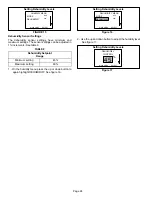
Page 24: ...1 increments See table 9 TABLE 9 Dehumidity Setpoint Range Minimum setting 45 Maximum setting 60 1 On the humidity menu press the up or down button to again highlight DEHUMIDIFY See figure 16 Setting Dehumidity Levels Figure 16 DEHUMIDIFY MENU MAIN MENU SELECT MODE DEHUMIDIFY OFF 45 2 Use the up and down button to adjust the humidity level See figure 17 Setting Dehumidity Levels Figure 17 DEHUMIDI...

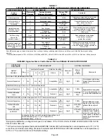
Page 25: ...gh speed compressor operation at begin ning of next cycle If humidity increases significantly over setpoint or if slide switch is moved unit immediately goes into dehumidification mode in presence of thermostat de mand TABLE 10 Reduced blower speed dehumidification speed begins imme diately with thermostat demand Dehumidification mode high speed com pressor begins with next thermostat de mand afte...

Page 26: ...egins when relative humidity is greater than setpoint TABLE 12 CBX32MV SignatureStat or ComfortSense 7000 and SINGLE STAGE OUTDOOR UNIT OPERATING SEQUENCE SYSTEM DEMAND SYSTEM RESPONSE System Condition Step Thermostat Demand Relative Humidity Compres sor Blower CFM COOL Comments Y1 O G W 1 Status D NO CALL FOR DEHUMIDIFICATION Normal Operation 1 On On On Acceptable 24 VAC High 100 Compressor and i...

Page 27: ...oom space to maintain a cooler room thermostat setpoint ROOM THERMOSTAT CALLS FOR FIRST AND SECOND STAGE COOLING BASIC MODE only active on a Y1 thermostat demand Normal Operation 1 On On On On Acceptable 24 VAC High 100 SignatureStat energizes Y2 and de energizes D on a call for dehumidification Dehumidification Call 2 On On On On Demand 0 VAC High 60 65 70 PRECISION MODE operates independent of a...

Page 28: ...place B Upflow Application 1 Discard drip shields if applicable The shields are used for downflow applications only and are located with the foam pads on top of unit 2 For best efficiency and air flow the horizontal drain pan should be removed from units in upflow configurations 3 After removing horizontal drain pan place unit in desired location Set unit so that it is level Connect return and sup...

Page 29: ...eplace coil access panel If horizontal drain pan is not removed depress tab in cabinet support rail to hold horizontal drain pan in place See figure 19 7 Set unit so that it is level Connect return and supply air plenums as required using sheet metal screws NOTE For downflow application metal or class I supply and return air plenums must be used For downflow installation on combustible flooring an...

Page 30: ...er above or below so that the full length of the cabinet is supported Use securing screws no longer than 1 2 13mm to avoid damage to coil or filter See figure 25 Connect return and supply air plenums as required using sheet metal screws NOTE For horizontal applications in high humidity areas remove the downflow rail closest to the drain pan Removal of downflow rail will prevent sweating in high hu...

Page 31: ... other The 90_ bend must be on the same side as the horizontal drain pan See figures 26 and 27 NOTE Use extreme care when re installing screws into coil end plate engaging holes Coil damage could result by misalignment FIGURE 26 FIELD MODIFICATION FOR LEFT HAND DISCHARGE 3 4 5 5 2 6 7 8 8 90_ BEND 9 CABINET SUPPORT COIL SHOWN IN UP FLOW POSITION FOR EASY CONVERSION FIGURE 27 90_ BEND 8 BACK COIL E...

Page 32: ...m of drain line to offset friction 5 An open vent in drain line will sometimes be required due to line length friction and static pressure 6 Drains should be constructed in a manner to facilitate future cleaning and not to interfere with filter access See figure 30 7 Auxiliary drain should run to an area where homeowner will notice it draining Refer to local codes VII START UP OPERATION A Prelimin...

Page 33: ...ts 7 Seal around the holes when the check is complete IX MAINTENANCE WARNING Electric shock hazard Can cause injury or death Before attempting to perform any service or maintenance turn the electrical power to unit OFF at discon nect switch es Unit may have multiple power supplies At the beginning of each heating cooling season the system should be checked as follows A Filters IMPORTANT Filter acc...

Page 34: ...f used HEATING 3 When there is a call for heat W1 of the thermostat energizes the electric heat relay K32 covered in the electric heat section After K32 closes blower relay K20 1 is energized 4 Blower motor B3 is energized on heating speed after K20 1 closes see electric heat 5 Economizer relay K20 2 if used is energized after K32 1 closes see electric heat section 6 K20 2 closes energizing the ec...

Page 35: ... DEMAND BLOWER SPEED Single Speed Condensing Unit Y1 to Y2 O to R See table 12 Two Speed Condensing Unit O to R See table 13 Single Speed Heat Pump Y1 to Y2 See table 12 Two Speed Heat Pump NONE See table 13 CBX32MV COOLING OPERATION AND JUMPER SUMMARY OPTIONAL ACCESSORIES WITHOUT SignatureStat OR CCB1 WITH HARMONY UNIT JUMPERS SEQUENCE OF OPERATION Single or Two Speed Condensing Unit O to R Harmo...

Page 36: ...C 2 When K32 1 closes the blower is energized on heating speed and economizer heat relay K20 2 is energized see unit schematic figure 26 3 Assuming the N C primary S15 and secondary S20 limit switches are closed electric heat element HE1 is energized 4 When K32 2 closes assuming the N C primary S15 and secondary S20 limit switches are closed electric heat element HE2 is energized ...

Page 37: ... unit schematic figure 26 3 Assuming the N C primary S15 and secondary S20 limit switches are closed electric heat element HE1 is energized SECOND STAGE HEAT remove jumper between W2 and R 4 When K32 2 closes the unit is ready for a second stage heat demand W2 of the thermostat sends a second stage heat demand energizing the electric heat relay K33 with 24VAC 5 When K33 1 and K33 2 close assuming ...

Page 38: ...f the thermostat sends a second stage heat demand energizing the electric heat relays K33 and K116 with 24VAC 5 When K33 1 closes the blower if not energized is energized on heating speed and economizer heat relay K43 is energized see 208 230VAC CB schematic 6 When K33 2 and K116 1 close assuming the N C primary S15 and secondary S20 limit switches are closed electric heat elements HE3 and HE6 are...

Page 39: ...ric heat relays K32 and K33 with 24VAC 2 When K32 1 and or K33 1 closes the blower is energized on heating speed and economizer heat relay K20 2 is energized see unit schematic figure 26 3 When K32 1 K32 2 and K33 2 closes assuming the N C primary S15 and secondary S20 limit switches are closed electric heat elements HE1 HE2 and HE3 are energized ...

Page 40: ...nergized 4 When K34 1 closes assuming the N C primary S15 and secondary S20 limit switches are closed electric heat element HE3 is energized SECOND STAGE HEAT remove jumper between W2 and R 5 When K34 2 closes the unit is ready for a second stage heat demand W2 of the thermostat sends a second stage heat demand energizing the electric heat relays K33 and K35 with 24VAC 6 When K33 1 closes the blow...

Reviews: