background image

506794-01

Page 6 of 16

Issue 1243

Combustion and Ventilation Air

Adequate provisions for combustion air, ventilation of 

furnace, and dilution of the gases must be made. When a 

furnace is installed in an unconfined space in a building, it 

can be assumed that infiltration will be sufficient to supply 

the required air.

If  the  furnace  is  installed  in  a  confined  space  and 

combustion air is taken from the heated space, the supply 

air and ventilating air must be through two permanent 

openings  of  equal  area.  A  confined  space  is  “a  space 

whose volume is less than 50 cubic feet per 1000 btu per 

hour of the combined input rating of all appliances installed 

in that space.” One opening must be within 12” of the 

ceiling and the other within 12” of the floor. Each opening 

must have a minimum free area of at least 1 square inch 

per 1000 btu per hour of total input rating of all appliances 

with the space but not less than 100 square inches.

If the furnace is installed in a space within a building of 

tight construction, air must be supplied from outdoors. In 

this case, one opening shall be within 12” of the ceiling and 

the other within 12” of the floor. If vertical combustion ducts 

are run, each opening must have a free area of at least 1 

square inch per 4000 btu per hour. If horizontal combustion 

ducts are run, 1 square inch per 2000 btu per hour of the 

total input of all appliances is required.

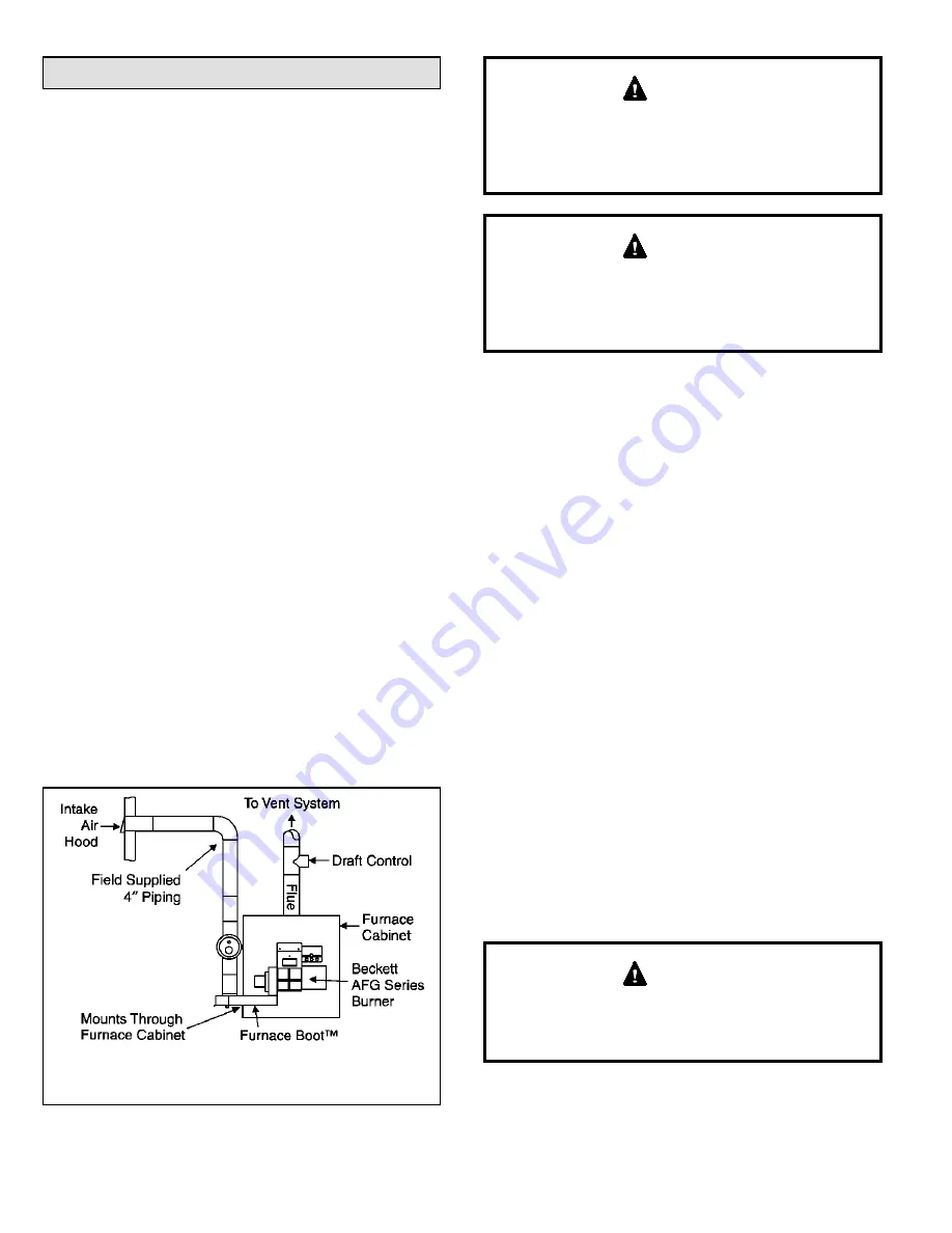
The furnace is designed to use air inside the dwelling 

for combustion. If additional combustion air is required, 

installing fresh air kit ABOOT571 allows air from outside 

the dwelling to be brought in to the oil burner. This kit brings 

air into the burner through air inlet ductwork run through 

the furnace cabinet side panel and terminated outside the 

dwelling (see Figure 5). The kit includes a vacuum relief 

valve to guard against combustion problems associated 

with directly connecting oil burners to the outside.

Figure 5. Fresh Air Kit ABOOT571 Installation

IMPORTANT

: No more than 10’ of vertical piping allowed without 

weight support.

Combustion air openings in the front of the furnace 

must be kept free of obstructions. Any obstruction will 

cause improper burner operation and may result in a 

fire hazard or injury.

   WARNING

The barometric control shall be in the same atmospheric 

pressure zone as the combustion air inlet to the furnace. 

Deviation from this practice will cause improper burner 

operation and may result in a fire hazard or injury.

   WARNING

Circulating Air Supply

A return air duct system is recommended. Where there is 

no complete return air duct system, a return connection 

should be run full size to a location outside the confined 

space and completely sealed so that no air from the 

confined space can be circulated through the heating duct 

system.

Outdoor Make Up Air

A minimum mixed return air temperature of 60 - 65°F 

must be maintained for outdoor make up air to prevent 

condensation and corrosion.

Venting

Chimney

Before installing the furnace, a thorough inspection of the 

chimney should be made to determine whether repairs 

are necessary and that the chimney is of the proper size 

and constructed in accordance with the requirements 

of the National Board of Fire Underwriters or Canadian 

Standards Association. The smallest dimension of the 

chimney should be at least equal to the diameter of the 

flue pipe of the furnace. Be sure the chimney will produce 

a  steady  draft  sufficient  to  remove  all  the  products  of 

combustion from the furnace. A fabricated vent system the 

same size as the flue outlet of the furnace may also be 

used. If a manufactured vent is used, it must be listed for 

use with oil-fired equipment.

This furnace is certified for use with Type “L” vent, Type 

“A”, and “factory-built” chimneys. “B” vent must not be 

used with oil furnaces.

   WARNING

Summary of Contents for Allied Air L83BF

Page 1: ... for any other storage purposes Such uses may result in actions that could cause property damage personal injury or death WARNING The installation of the furnace wiring warm air ducts venting etc must conform to the requirements of the National Fire Protection Association Standard for the Installation of Oil Burning Equipment NFPA No 31 the National Electrical Code ANSI NFPA No 70 in the USA the I...

Page 2: ...____ Two pipe ___________________ c Distance from tank __________________ Lift __________________ d Filter type _____________ Inspect __________ Change _________ e Pressure test ___________________________________________ f Recheck all fittings for tightness _____________________________ Thermostat a Type Heating __________________ Cooling __________________ b Anticipator set _____________________...

Page 3: ... or access opening should be large enough to permit replacement of the furnace or another appliance such as a water heater without disturbing any other equipment In any installation where damage from oil may occur a drain pan must be installed The drain pan must be large enough size to completely prevent any potential oil damage The drain pan piping must be sized to drain the oil pump capacity and...

Page 4: ...f installation requires that the flow be reversed follow these steps 1 Rotate the furnace 180 so that the warm air is discharged out the right side 2 Remove the oil burner and the screws securing the burner mounting plate Rotate the burner mounting plate 180 and reattach with screws Remount the burner in the upright position 3 Remove the screws holding the limit control in place Relocate the limit...

Page 5: ...Flooring 12 minimum Cold Air Duct Blower Comparment Combustible Floor Base Sub base Insulation Model Size Downflow Cold Air Duct size Warm Air Plenum Size Floor Hole Size Wood Floor Hole Size Slab Combustible Floor Base Kit Number 57 72 84 95 18 1 4 X 18 1 4 18 1 4 X 18 1 4 19 X 19 18 1 2 X 18 1 2 ABASE 537 1 112 125 21 1 4 X 21 1 4 21 1 4 X 21 1 4 22 X 22 21 1 2 X 21 1 2 ABASE 538 1 Figure 4 Comb...

Page 6: ...a vacuum relief valve to guard against combustion problems associated with directly connecting oil burners to the outside Figure 5 Fresh Air Kit ABOOT571 Installation IMPORTANT No more than 10 of vertical piping allowed without weight support Combustion air openings in the front of the furnace must be kept free of obstructions Any obstruction will cause improper burner operation and may result in ...

Page 7: ... to a factory built chimney or vent complying with a recognized standard or a masonry or concrete chimney lined with a lining material acceptable to the authority having jurisdiction 11 When two or more appliances vent into a common flue the area of the common flue should not be less than the area of the largest flue or vent connection plus 50 of the areas of the additional vents or flue connectio...

Page 8: ...vice parts information Figure 9 Horizontal Venting Front Flue Rear Flue Barometric control must be installed in the horizontal venting system and located within 18 of the flue outlet of the furnace Barometric draft control must be used in the horizontal venting sidewall system It must be located within 18 of the furnace flue outlet see Figure 9 Do not common vent with any other appliance when usin...

Page 9: ...ion or CAN CGA B149 1 2 Installation Codes to correct improper operation of common venting system Smoke Pipe and Draft Control Connect the furnace vent to the chimney with galvanized smoke pipe and fittings maintaining full diameter of furnace vent throughout No reduction in diameter of pipe is allowed It is best to have smoke pipe as short and direct as possible The smoke pipe shall maintain a ri...

Page 10: ...e care when installing the oil burner so that the chamber is not damaged around the burner tube To enable the continuous blower operation place the fan switch on the thermostat into the ON position A call for fan from the thermostat closes R to G on the blower interface board The control waits for a 1 second thermostat debounce delay before responding to the call for fan by ramping the circulating...

Page 11: ... remain in the position A B C or D listed in the HEAT Setting column found in Table 2 ADJUST HEAT and COOL Taps on Blower Interface Board DEHUMIDIFY CUT TO ENABLE COOL HEAT ADJUST NORM A B C D A B C D TEST D1 Placing ADJUST jumper plug in the TEST position energizes the motor to a default factory setting This can be used to determine if the motor is operating properly Test pin function is enabled ...

Page 12: ...adjustment to this furnace and its components must be done by a qualified service technician Refer to Table 3 for nozzle and pump pressure information The proper way to adjust an oil burner is with a CO2 analyzer and a smoke gun A properly adjusted burner will result in a quiet clean fire which will prevent sooting and frequent cleaning Using the following procedure will provide a margin of reserv...

Page 13: ...n the depth is correct the tip of the nozzle should just touch the base of the T gauge 2 Nozzle adjustments are made by sliding the entire nozzle assembly forward or backward within the blast tube see Figure 12 To check nozzle alignment 1 Insert the small end of the T gauge into the end of the cone and measure the nozzle and electrode alignment against the center lines marked on the gauge 2 If the...

Page 14: ...1st stage cooling demand passive dehumidification mode After 7 5 minutes the blower motor runs at 70 of the selected cooling air flow until 1st stage cooling demand is satisfied A call for 2nd stage cooling from the thermostat closes the R to Y2 circuit on the blower interface board The blower motor ramps up to 100 of the selected cooling air flow When the demand for cooling is met the blower ramp...

Page 15: ... to reinstall the locking screws 7 Brush out and vacuum the vent outlet area of the outer drum and reattach the vent pipe 8 Clean up around burner blower deck and vestibule area Heat exchanger cleanout kit ABRSH380 3 is available from the manufacturer Emergency Replacement Motor Operation If the variable speed motor in this furnace needs to be replaced in an emergency situation such as no heat and...

Page 16: ...506794 01 Page 16 of 16 Issue 1243 Figure 17 Wiring Diagram P N 48252 001 ...

Reviews: