Lencore GOLD A1U Design, Installation And Operation Manuallines Download Page 36

Setting the IP Settings

1.

If using the SMC Toolbox application, follow the steps above to change or view IP settings

2.

If not using the SMC Toolbox application, power on the Head End and wait about 2

minutes. (The AUX


LED will be flashing while booting up, and solid once complete.

3.

Click the "Func" button on the front of the Head End until you get to the "IP Info" section.

4.

The current IP address will be displayed.

5.

Use the "Opt" button to cycle through additional IP settings including: Subnet, Gateway,

and MAC ID.

6.

We can also change the IP settings by navigating the IP address displayed on the Head

End display.

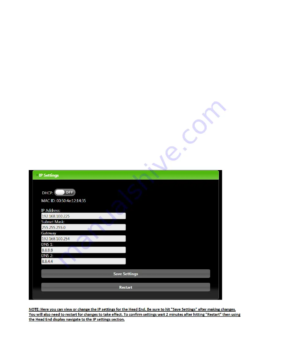
Changing the IP Settings using the System Manager Webpages

1.

Make sure your static IP is set on your PC and you have internet connection going from

your PC to


the "Protocessor Field Pop Enabled" port on the back of the Headend. (See

Interfacing with the


protonode section of the manual for further instructions).

2.

Open a web browser and enter the Headend IP address.

3.

On the Lencore landing page, select the "Systems Setting" option.

33

Summary of Contents for GOLD A1U

Page 1: ...GOLD DESIGN INSTALLATION AND OPERATION GUIDELINES Model A1U...

Page 2: ...ram Wiring Connections Configuring the System Flow Diagram System Zoning Speaker Layout Installation IR Wall Controls Tuning and Balancing Changing the IP Address Operating the System from the Front P...

Page 3: ...ectrician for replacement of the obsolete outlet 10 Protect the power cord from being walked on or pinched particularly at plugs convenience receptacles and the point where they exit from the apparatu...

Page 4: ...ation and total control in one unit The Gold unit is a 1RU rack mount unit that offers two Operating Platforms OPs and a head end in one unit The system maintains the easy to use full one third octave...

Page 5: ...erence in the way that the sound is dispersed there are different design and layout guidelines based on which speaker system is being used Allspeakers are powered through the headend device via Cat5e...

Page 6: ...uration information about the system 5 GND For external auxiliary equipment 6 OP1 speaker connectors Speaker connectors for OP1 channels A B C and D using RJ45 connectors 7 IR Inputs Connect the IR in...

Page 7: ...ready 2 Connect a network cable to the unit s Ethernet input to access the Protocessor The Protocessor is the network server The Protocessor is pre loaded with Lencore s System Manager System Manager...

Page 8: ...Connect an IR unit to the IR port IR1 for OP1 speakers IR2 for OP2 speakers Speaker connections 1 Connect the external speakers to the appropriate channel using cat 5 RJ45 cables IR 1 IR 2 CH 1A CH 1...

Page 9: ...re and adjust the system for many functions System Manager must be used to create any zones or to make more detailed adjustments such as equalizer settings See below for switches usage and System Mana...

Page 10: ...a total of 64 speakers Interconnect cables are utilized by both types of speakers Connect the Output jack of a previous speaker to theInput jack of the next speaker in a daisy chain fashion Cable Cabl...

Page 11: ...nes In cases where variation in ceiling heights of greater than 6 occur multiple zones are required withinthe same functional space to meet the goal of a consistent sound masking signal being delivere...

Page 12: ...any direction to avoid the conflict However ensure that the most consistent spacing possible is achieved to keep variations to a minimum OpenAreaDirectFiredSpeakerSpacingRequirements Speaker Mounting...

Page 13: ...speaker location centered in the ceiling tile The above example shows a 10 x 8 grid in use in 2 x4 ceiling tiles to accomplish this goal This approach may be used in cases where ceiling height would...

Page 14: ...ing deployment See Table 2 It is preferred that hallway corridor areas be treated as a separate sound masking zone to allow for independent level adjustment in most applications This is especially imp...

Page 15: ...ntual failure Rubber feet are available to place the unit on a shelf or desk if a rack is not available Contact Lencore for more information at 516 682 9292 or info lencore com WALL MOUNTED 1 Unscrew...

Page 16: ...its INPUT only There will be no cable connected to the output Note If a tile bridge is being installed After hole is cut in the tile lay tile bridge across the suspension grid Push the torsion springs...

Page 17: ...INSTALLATION DIAGRAMS Top Bottom Side 14...

Page 18: ...C L For additionalTechnical Support call 516 682 9292 INSTALLATION DIAGRAMS Tile Bridge TB4 Not Shown 15...

Page 19: ...ion to OP Connect the audio cable 8 conductor CAT5 from OP channel to INPUT of speaker 2 For speaker to speaker connection Connect audio cable 8 conductor from OUTPUT of previous speaker to INPUT of n...

Page 20: ...Gold Decorative Pendant Speaker installation diagram 4 x 1 5 17...

Page 21: ...ing codes for allowable hanging methods and standards 4 Drive a nail holding the clip with the speaker chain and speaker into deck INSTALLATION INSTRUCTIONS FOR THE GOLD IN PLENUM UNIVERSAL SPEAKER Fo...

Page 22: ...INSTALLATION DIAGRAMS 0 0 19...

Page 23: ...oard see diagram The list below shows all possible configurations for the IR Touch Pad Configurations will allow you to control individual channels such as Channel A B C D individually or ALL Channels...

Page 24: ...l G482 out of the box If you do not have the IR Hub model G482 you can connect the IR touch pad directly to an OP This will require configuration IR touch pad can control one individual channel or all...

Page 25: ...Channel B Only No Hub Direct to OP IR Port 2 UP All else DOWN Channel C Only No Hub Direct to OP IR Port 3 UP All else DOWN Channel D Only No Hub Direct to OP IR Port 4 UP All else DOWN Ch A B C D ON...

Page 26: ...to take baseline readings on your S P meter Mark these measurements down for each area Different spaces such as hallways open work rooms closed rooms etc treat sound differently and will need to be t...

Page 27: ...ChangeAdapterSettings The computer must be configured properly with an IP Address that is different from the device Follow this sequence AccessNetworkSettings 24...

Page 28: ...Highlight InternetProtocolVersion4 TCP IPv4 andclickProperties RightclickonyourEthernetconnection ClickProperties Right Click then Click Properties 25...

Page 29: ...Click UsethefollowingIPAddress radialbuttonandtypeinthefollowing 192 168 100 200Itshouldlooklikethefollowing Click OK andexitoutofset up 26...

Page 30: ...ings are Username comfort Password comfort After logging in you will be presented with five tabbed options to select from Devices allows you to select the OP for System Volume and Contour adjustments...

Page 31: ...Clicking on an OP will bring up the Controls and Tabs for that OP 28...

Page 32: ...ume and contour frequency controls Always check your levels If your decibel levels are too low the space may feel comfortable however you will not be effectively masking speech FinalStep Once you have...

Page 33: ...of all of the zones that have been added to the system for the selected zone type as well as a button for adding a new zone of the selected type Each individual Zone item consists of the following inf...

Page 34: ...he Basic Settings link you have the ability to name the zone in order to more easily identify which area you are adjusting The Zone Name will be identified in the brackets next to the Zone i e in this...

Page 35: ...e zone NOTE In most instances the equalizer should not be adjusted unless there is a specific curve you want to apply Lencore sets the masking at a comfortable curve out of the box You have the flexib...

Page 36: ...e Opt button to cycle through additional IP settings including Subnet Gateway and MAC ID 6 We can also change the IP settings by navigating the IP address displayed on the Head End display Changing th...

Page 37: ...n IP Address Automatically radial button and click Ok Your set up is now complete Enjoy your Gold System and the best sound masking in the market If you have any questions or need assistance our team...

Page 38: ...used to select operations To use the keypad first choose the FUNCTION of operation After the function has been selected use the OPT key to select the option Finally use the up and down arrows to chang...

Page 39: ...alue to change OP number channel letter or volume Both OP s OP ALL or individual OP s OP1 or OP2 or individual channels A B C D can be selected Use the up and down arrows to increment and decrement th...

Page 40: ...SEL button until the curser is on the value to change Clear Mute Fault number Use the up and down arrows to scroll through the fault list If the curser is on Clear or Mute the up or down arrow will c...

Page 41: ...Ds is on a system fault has occurred Front Panel Indicators Neuron activity The Neuron is a specialized internal microprocessor The LEDs labeled TX and RX indicate Neuron activity These LEDs will be f...

Page 42: ...lay RL1 is de energized AUX LED is for future use Protocessor The Protocessor LEDs indicate the state of the Protocessor The ERR LED will go on solid 15 seconds after power up It will turn off after 5...

Page 43: ...16 682 9292 info lencore com www lencore com The information contained herein is proprietary to Lencore Acoustics LLC and copyright protected No part of this manual can be copied used or distributed w...

Reviews: