


25
SERVICE (DC-2000)
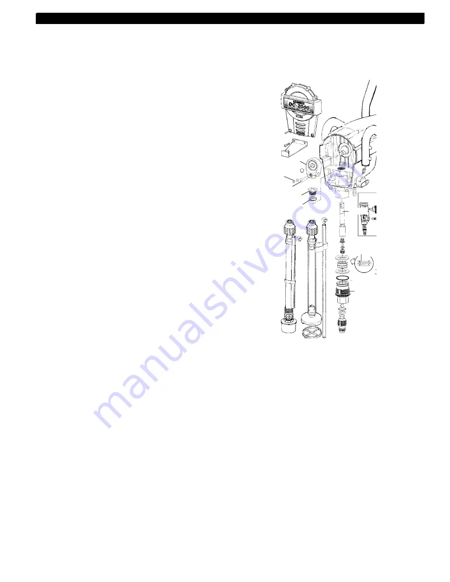
connecting
pin
inlet
valve
housing
top nut
yoke
screw and
washer
upper packing
piston
lower
packing
Packing kit #L045-651 consists of: top nut, upper
& lower packings, shaft & inlet valve balls, inlet
housing o-ring, seals & spacer for inlet seat.
DAILY MAINTENANCE
To only daily maintenance necessary is thorough cleaning. Follow the
cleaning procedures in this manual.
EXTENDED MAINTENANCE
Some pump parts eventually wear out from use and must be replaced.
The following list indicates the available repair kits for the parts replaced
by each kit. However, pump performance is the only reliable indicator of
when to replace wear parts. Refer to the troubleshooting section for
more information on when to use these kits.
WARNING: While performing this step, keep one hand on the cart and
the other on the ON/OFF switch. Never put body parts or tools into
operating pump area. Do not wear clothing that may get caught in
working parts of the pump.
Note: Indexing can be done by temporarily plugging in the unit and
turning the ON/OFF switch on, then immediately off. Repeat this ON/
OFF procedure until the yoke comes to a stop near the top of its stroke.
Unplug the unit before proceeding.
4. Remove the screw and washer that secure the connecting pin in
position.
5. Using a pliers, pull out the connecting pin.
6. Using a wrench, unscrew and remove the inlet valve assembly.
7. Remove the piston assembly. This can be done by pushing down on
the piston near the yoke.
8. Using a wrench, unscrew and remove the top nut.
9. CAUTION: Be careful not to score the cylinder with the screwdriver
during removal of the old packings.Using a flat head screwdriver,
carefully remove the old upper packing from the pump housing.
Push the packing up and out from the bottom. Push the lower
packing down and out from the top.
10. Clean the area where the new packings are to be installed
Assembling the Fluid Section
1. Lubricate the new packings with light household oil and install into
the pump housing. Push the upper packing into the top of the pump
housing. Push the lower packing into the bottom of the pump
housing.
2. Insert the piston assembly through the bottom of the pump housing.
Push the piston up enough so that the hole in the piston is aligned
approximately with the hole in the yoke.
3. Place the new o-ring onto the inlet valve assembly and thread the
inlet valve assembly into the bottom of the pump housing.
4. Thread the new top nut into the pump housing and tighten securely.
DO NOT reuse the old nut, the slightest wear in the nut will allow the
piston to sway and cause the new packings to wear prematurely.
5. Connect the piston to the yoke by pushing the connecting pin into
position. The piston will have to be moved up or down to align the
holes.
6. Reassemble the yoke screw and washer that secure the connecting
pin.
7. Apply approximately one teaspoon of oil or light household oil to the
top nut. The three ports in the nut allow oil to lubricate the upper
packing. This will prolong packing life.
8. Place the front cover over the pump housing. Screw in the four
screws that secure the front cover.
9. Attach the suction set to the inlet valve assembly.
Summary of Contents for DC1600
Page 31: ...31 NOTES...