ProVision 3 Installation Manual
8100-35521-00
Rev. A1
Leidos Security Detection & Automation, Inc.
–
Proprietary
Page 29 of 119
© 2020 Leidos. All rights reserved
2.
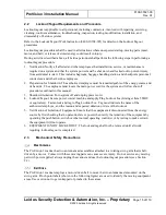
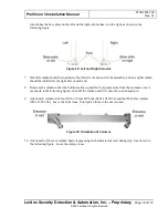
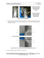
After the caster assemblies are attached to the upper/lower frame assembly (described in next
chapter), they are moved to the open position by ensuring the two quick-release pins are removed,
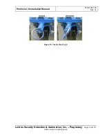
then inserting the leverage bar into the square tube in the center of the caster swing plate. The caster
must be correctly oriented with the wheel bracket nearly vertical, as shown in Figure 17, before
applying pressure on the leverage bar.
Figure 17: Caster Orientation
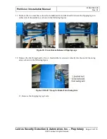
3.
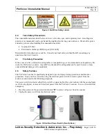
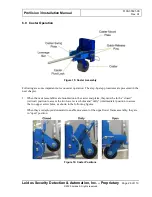
Keep
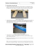
hands, fingers, and any other body part, tool or other items clear of the “
Caster Caution Area
”
between the caster mount plate and the caster swing plate at all times when leveraging the caster
swing plates downward and lifting the weight of the scanner assembly. Both caster swing plates on
the end being raised must be leveraged downward at the same time by two technicians.
Figure 18: Caster Caution Area
4.
The quick-release pins are re-inserted into their holes once the caster swing plates are leveraged
downward to lock them into place.
5.
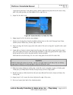
Each caster can be locked in a fixed direction or unlocked to swivel freely, enabling direction changes
when moving the scanner. To switch from locked to unlocked, pull the spring-loaded ring out of the
deep groove (see following figure), rotate the ring 90 degrees to the shallow groove and release it.

