background image


Last Updated on Sep 2021 

Click on 

Live

 to view a live image. You can now adjust parameters while checking the result 

directly on the monitor. Be careful though, if you spend too long doing this you will 
photobleach your sample. Start focusing your sample and then center it moving the stage. 

Now, based on the image, you can adjust the brightness in the 

Acquire

 and 

Acquisition

 tabs: 


Excitation 

laser power

: the higher the laser power, the faster your sample photobleaches. 

Also, this will alter both the brightness of the fluorescent image and that of the brightfield. 


Gain

:  

o


Photomultiplier Tube (PMT): 

Keep below 800V during image acquisition to control 

noise.  

o


Hybrid Detector (HyD):

 Keep at 100% at all times for optimum performance. Change 

the brightness of your image by changing the laser power only.   


Offset

 (adjusts the background/black level) 


Pinhole

 (the wider the pinhole aperture, the thicker is the optical slice 

 which means a 

blurrier, but brighter image). 

Make sure you also lower the laser power if you have to 

increase the pinhole. 


There’s no general rule: these adjustments mainly depend on your sample.


4.8 Image Adjustments 

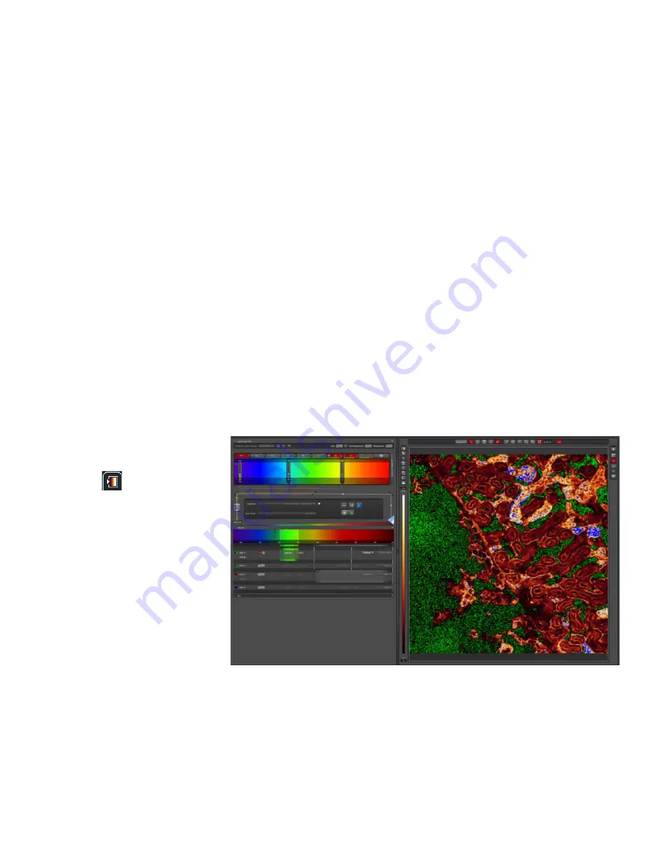
 Setting the Gain and Offset properly


Check image saturation 
level by clicking QuickLUT 

icon 

. The image will 

change color to show 
green, orange and blue. 
Green indicates that the 
signal in a given pixel is 
black, with a value of 0. 
Blue color in a given pixel 
means it is saturated (over-
exposed) with a value of 
255. We need to bring our 
image back within the 
limits of our dynamic range, such that the background is black and the sample is not too bright. 
Different sets of experiments may have different fluorescence intensities. 

When using the PMT detectors, we have to adjust our image using a combination of the 
excitation 

Laser power

Gain

 and 

Offset

: Set the Gain at 700 - 800 and reduce it, or the laser 

Summary of Contents for TCS SP8

Page 1: ...ng and System Access 5 3 1 Acknowledgements 6 4 Operation Procedures 6 4 1 Switching ON Protocol 7 4 2 Objective Lens 7 4 3 Software initiation 8 4 4 Turning on the lasers 8 4 5 Using Dye Assistant ta...

Page 2: ...Last Updated on Sep 2021 THIS PAGE IS INTENTIONALLY LEFT BLANK...

Page 3: ...ensure the lasers have sufficient time to heat up and cool down before running again When using the lasers to image NEVER look directly at the laser while imaging If a safety shutter is present make s...

Page 4: ...hen you notice that a bulb has reached between 2 000 2 500 hours or is not functioning properly 2 Training Use of confocal microscopy and the online booking system is authorized by facility staff only...

Page 5: ...week but it has to be shared across the systems that they have received training on Each booking must not exceed 3 hours If users have utilized all their entitled bookings for the week 24Hr Rule can b...

Page 6: ...Operation Procedures Every confocal system in TLL Bioimaging Facility has its specific instructional manual which are found in every confocal rooms Strictly adhere to the correct order of operation fo...

Page 7: ...re ON for a minimum of 2hrs before switching OFF as it requires sufficient time for warming up STED laser You may switch ON up to 100 Make sure the STED lasers are ON for at least 1hr before switching...

Page 8: ...4 4 Turning on the lasers 1 Under the Visible panel click on the button to open the laser panel 2 Click on the UV 405nm Visible Argon and SuperContVisible2 WLL bar to observe 405nm Argon and WLL respe...

Page 9: ...ector HyD or PMT you would like to image with your dyes HyD is more sensitive than PMT 4 The Dye assistant will give you a list of laser settings options to select from Select the settings which has t...

Page 10: ...our fluorophore Important Make sure that the emission band is at least 8 10nm away from your excitation line Choose an appropriate detector pseudocolour also known as a Look Up Table or LUT For PMT se...

Page 11: ...tional X Useful for live imaging unless you require fast imaging in which case you will need to adjust the phase correction Zoom is where you control the zoom parameters the arrows allow you to nudge...

Page 12: ...e background black level Pinhole the wider the pinhole aperture the thicker is the optical slice which means a blurrier but brighter image Make sure you also lower the laser power if you have to incre...

Page 13: ...3D Image Scroll down to the Z stack option in the Acquisition tab Select Live to see the specimen Use the focus knob on the USB control panel or point the cursor in the Z stack box panel and use the m...

Page 14: ...e any images which are older than 3 months Please make sure to do a backup Option 2 In TLL research cmn drive folder in your respective lab folders Option 3 In your own lab drive Option 4 In your pers...

Page 15: ...ethanol to remove any oil residues e In the event of logging off you may leave the lasers ON and exit LASX Otherwise Switch off all lasers within the software Diode Laser OFF 405nm White Light laser...

Page 16: ...s issue is a scanner issue you will not hear clicking as the program is shutting down and performing its pre shutdown WLL checks 2 Switch off the LSM switch 3 marked Scanner 3 Switch on the LSM 4 Open...

Page 17: ...If it says the HyD overloaded use the following steps 1 Turn off Live View 2 Ensure that the detection band is set at least 10nm away from any laser you are using 3 Set the HyD gain to 100 always Brig...

Page 18: ...Last Updated on Sep 2021 5 1 Troubleshooting Appendix Switches under computer terminal Power schematic diagram of the SP8...

Reviews: